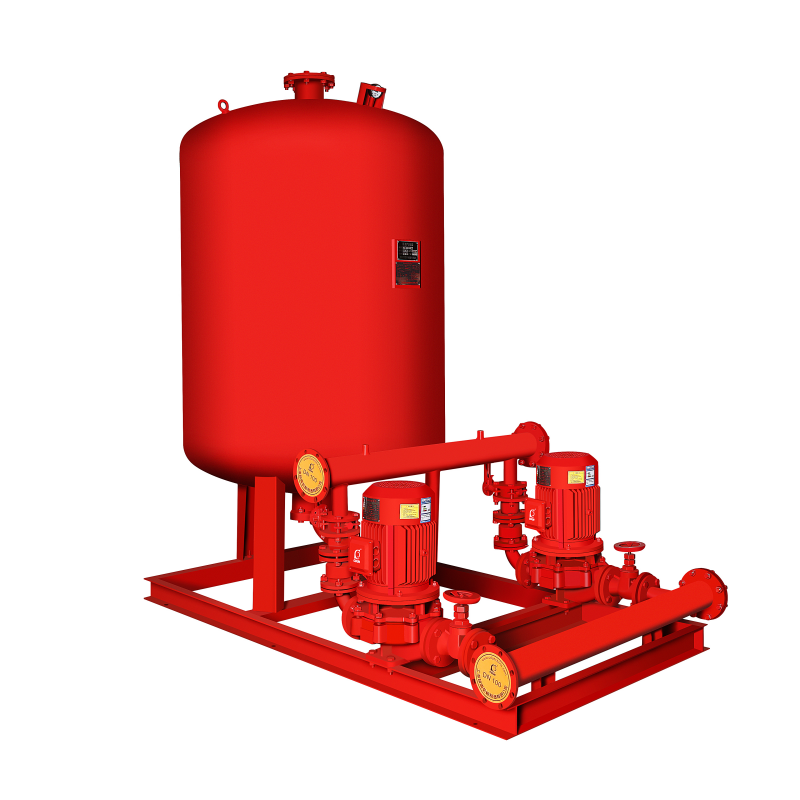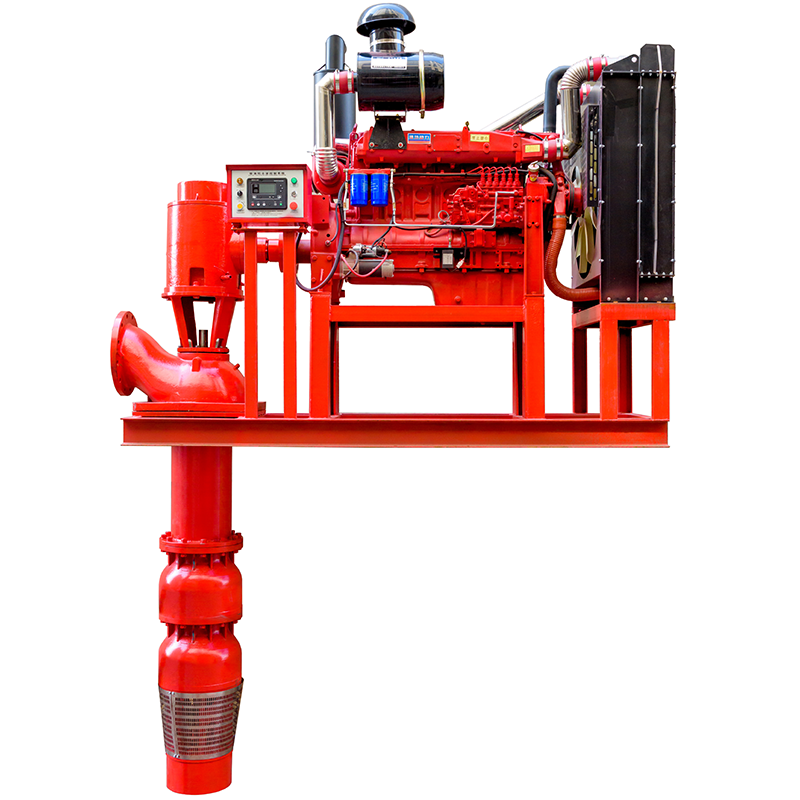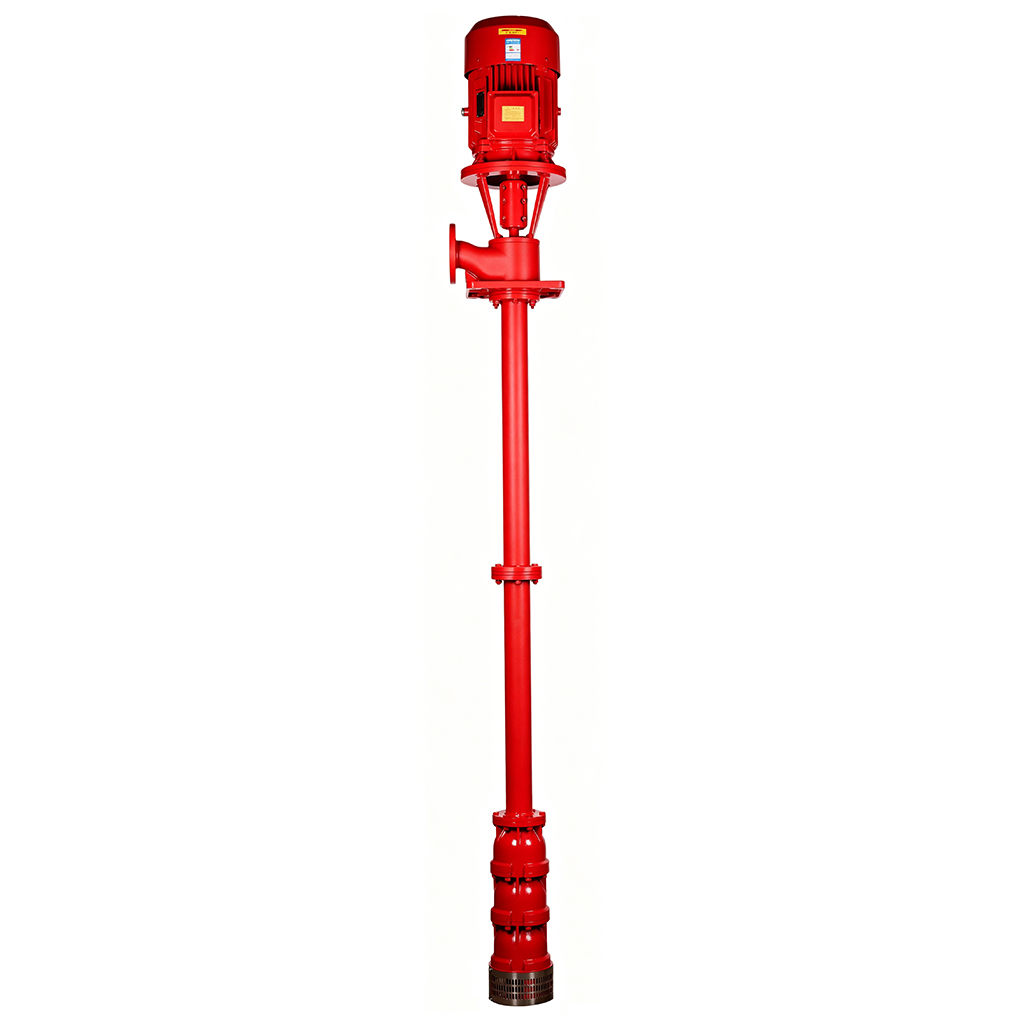

Product Overview
Traditional single-suction pumps suffer from high axial thrust, excessive vibration, and complex maintenance requiring full pipeline disassembly, increasing downtime and O&M costs in high-flow applications.
This series resolves these issues via a horizontally split-case, double-suction design with a statically balanced impeller and axial force self-balancing bearings. The top-access cover enables direct rotor inspection without disconnecting pipes or motors, while optional mechanical seals deliver high flow, low NPSHr, and reliable long-term operation.
Widely deployed in municipal water plants, industrial cooling, power generation, and large HVAC systems, it handles clean water ≤80℃ and abrasive media with customizable materials. Its rapid maintenance and stable performance establish a new industry benchmark for efficient split-case centrifugal pumps.
Product Advantages
Extended Service Life: Symmetrical double-suction impeller self-balances axial thrust with optimized bearings. Lifespan ≥15 years—35%+ longer than single-suction pumps.
Significant Energy Savings: Dual-suction inlet cuts flow velocity & NPSHr. Efficiency ≥85%, hydraulic losses ↓12–18%, reducing annual energy costs significantly.
Lower Maintenance Costs: Split-case cover with locating pins enables rotor extraction without pipe/motor disassembly. Seal/bearing inspection in 1.5h, cutting labor costs by 40%.
Lightweight & Compact Design: Streamlined cast iron casing + integrated base cuts footprint by 25%, reducing construction & lifting costs.
Faster Installation: Horizontally positioned ports + pre-aligned coupling enable stress-free pipe connection. Commissioning ready in 2h, accelerating deployment by 40%.
Application Scenarios
Municipal Water: Raw/clear water transport, main pipe boosting, stable high-flow supply.
Industrial Cooling: Power/chemical/metallurgical circulation, HVAC water loops, variable-flow energy saving.
Agriculture: Large-scale irrigation, river/reservoir lifting, sandy/muddy water compatible (wear-resistant options).
Public Facilities: Fire/AC water systems for stadiums/airports/data centers, low-noise, high environmental compliance.
Media: Clean water ≤80°C or similar. Sandy/muddy water: wear-resistant upgrades available. Packing/mechanical seal optional.
Technical Parameters
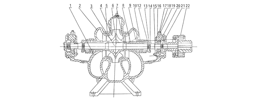
Product Structure Diagram
Type A Arrangement (Rolling Bearing)
 |
|||
| NO. | Component List | NO. | Component List |
| 1 | Pump Casing | 12 | Gland |
| 2 | Casing Cover | 13 | Sleeve Nut |
| 3 | Shaft | 14 | Stud Bolt |
| 4 | Impeller | 15 | Bearing Cover |
| 5 | Double Suction Wear Ring | 16 | Bearing Spacer |
| 6 | Key | 17 | Bearing Housing |
| 7 | Shaft Sleeve | 18 | Set Screw |
| 8 | Lantern Ring Sleeve | 19 | Bearing Housing Cover |
| 9 | Gland Packing | 20 | Bearing |
| 10 | Lantern Ring | 21 | Round Nut |
| 11 | Gland | 22 | Coupling Assembly |
Type B – Sleeve Bearing
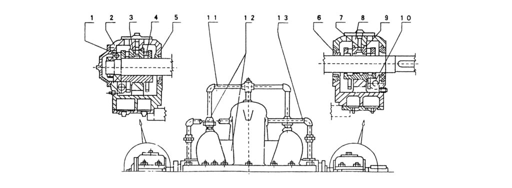 |
|||
| NO. | Component List | NO. | Component List |
| 1 | Ball Bearing | 8 | Type A Housing / Type A Cover |
| 2 | Type B Housing / Type B Cover | 9 | Type A Upper / Lower Bearing |
| 3 | Type B Upper / Lower Shell | 10 | Vernier Scale |
| 4 | Oil Ring | 11 | Vent Pipe |
| 5 | Bearing Seal Ring | 12 | Small Check Valve |
| 6 | Oil Deflector | 13 | Seal Flush Line |
| 7 | Dowel Pin | / | / |
Performance Data Table
Sh Series – Performance Data 1
|
Model |
Flow (Q) | Total Head H (m) | Speed n (rpm) | Shaft Power P (kW) | Efficiency % | Max. Allowable Suction Lift | Impeller Diameter | Weight (kg) | ||
| m³/h | L/s | Shaft Power | Motor Power | |||||||
| 6Sh-6
150S78 |
126
162 198 |
35
45 55 |
84
78 70 |
2900 | 40
46.5 52.4 |
55 | 72
74 72 |
5 | 248 | 150 |
| 6Sh-6A
150S78A |
112
144 180 |
31
40 50 |
67
62 55 |
2900 | 30
33.8 38.5 |
45 | 68
72 70 |
5 | 220 | 150 |
| 6Sh-9
150S50 |
130
170 220 |
36.2
47.2 61.2 |
52
47.6 35 |
2900 | 25.3
27.6 31.3 |
37 | 73.9
79.8 67 |
5 | 200 | 145 |
| 6Sh-9A
150S50A |
120
144 180 |
31
40 50 |
43.8
40 35 |
2900 | 18.5
20.9 24.5 |
30 | 72
75 70 |
5 | 186 | 145 |
| 8Sh-6
200S95 |
180
234 288 |
50
65 80 |
100
93.5 82.5 |
2900 | 81.8
86.3 91.1 |
110 | 60
69 71 |
4.5 | 284 | 245 |
| 8Sh-6A
200S95A |
160
215 265 |
44.5
59.7 73.6 |
85.1
75.6 70.2 |
2900 | 60.8
64.2 71.4 |
90 | 61
69 71 |
5.5 | 262 | 245 |
| 8Sh-9
200S63 |
213
288 351 |
60
80 97.5 |
69
62.5 50 |
2900 | 55
61.6 67.8 |
75 | 74
79.5 70.5 |
5.3
4.5 3 |
236 | 265 |
| 8Sh-9A
200S63A |
180
270 324 |
50
70 90 |
54.5
46 37.5 |
2900 | 41
48.3 51 |
55 | 65
70 65 |
5.5
5.0 3.8 |
220 | 265 |
| 8Sh-13
200S42 |
216
288 342 |
60
80 95 |
48
41.3 35 |
2900 | 34.9
38.1 40.2 |
45 | 81
85 81 |
5.0
3.6 1.8 |
204 | 219 |
| 8Sh-13A
200S42A |
198
270 310 |
55
75 86 |
43
36 31 |
2900- | 30.5
33.1 34.4 |
37 | 76
80 76 |
5.2
4.2 3.0 |
193 | 219 |
| 10Sh-6
250S65 |
360
486 612 |
100
135 170 |
71
65.1 56 |
1450 | 88.1
112 129.6 |
132 | 77
72 |
6 | 460 | 565 |
| 10Sh-6A
250S65A |
342
468 540 |
95
130 ·150 |
61
54 50 |
1450 | 72
86 98 |
110 | 79
80 75 |
6 | 430 | 565 |
| 10Sh-9
250S39 |
360
486 612 |
100 ·
135 170 |
42.5
38.5 32.5 |
1450 | 55.5
61.5 67.7 |
75 | 75
83 80 |
6 | 367 | 428 |
| 10Sh-9A
250S39A |
324
468 576 |
90
130 160 |
35.5
30.5 25 |
1450 | 40.2
45.7 47.8 |
55 | 78
85 82 |
6 | 338 | 428 |
| 10Sh-13
250S24 |
360
486 576 |
100
135 160 |
27
23.5 19 |
1450 | 33.1
36.2 36.4 |
45 | 80
86 82 |
6 | 296 | 420 |
| 10Sh-13A
250S24A |
342
414 482 |
95
115 134 |
22.2
20.3 17.4 |
1450 | 25.8
27.6 28.6 |
37 | 80
83 80 |
6 | 270 | 420 |
| 10Sh-19
250S14 |
360
486 576 |
100
135 160 |
17.5
14 11 |
1450 | 21.4
21.8 22.1 |
30 | 80
85 78 |
6 | 240 | 405 |
Sh Series – Performance Data 2
|
Model |
Flow (Q) | Total Head H (m) | Speed n (rpm) | Shaft Power P (kW) | Efficiency % | Max. Allowable Suction Lift | Impeller Diameter | Weight (kg) | ||
| m³/h | L/s | Shaft Power | Motor Power | |||||||
| 10Sh-19A
250S14A |
320
432 504 |
89
120 140 |
13.3
11 8.6 |
1450 | 15.4
15.8 15.8 |
22 | 78
82 75 |
6 | 224 | 405 |
| 12Sh-6
300S90 |
590
792 936 |
164
220 260 |
98
90 82 |
1450 | 213
250 279 |
300 | 74
77.5 75 |
5.4
4.5 3.5 |
540 | 847 |
| 12Sh-6A
300S90A |
576
755 918 |
160
210 255 |
86
78 70 |
1450 | 190
217 246 |
260 | 71
74 71 |
5.5
4.7 3.6 |
510 | 845 |
| 12Sh-6B
300S90B |
540
720 900 |
150
200 250 |
57 |
1450 | 151
180 200 |
260 | 70
73 70 |
5.6
4.9 3.8 |
475 | 845 |
| 12Sh-9
300S58 |
576
792 972 |
160
220 270 |
65
58 50 |
1450 | 127.5
150 167.5 |
180 | 80
83.5 79 |
4.5 | 435 | 572 |
| 12Sh-9A
300S58A |
530
720 893 |
147
200 248 |
55
49 42 |
1450 | 99.2
116 131 |
155 | 80
83 78 |
4.5 | 402 | 572 |
| 12Sh-9B
300S58B |
504
684 835 |
140
190 232 |
47.2
43 37 |
1450 | 82.5
97.7 108 |
135 | 79
82 78 |
4.5 | 378 | 572 |
| 12Sh-13
300S32 |
612
792 900 |
170
220 250 |
38
32.2 25.5 |
1450 | 76.2
80.3 78.1 |
90 | 83
86.5 80.1 |
4.5 | 352 | 809 |
| 12Sh-13A
300S32A |
550
720 810 |
153
200 225 |
31
26 20.5 |
1450 | 58.1
60.7 58 |
75 | 80
84 78 |
4.5 | 322 | 809 |
| 12Sh-19
300S19 |
612
792 935 |
170
220 260 |
23
19.4 14 |
1450 | 47.9
51 47.6 |
55 | 80
82 75 |
4.5 | 290 | 660 |
| 12Sh-19A
300S19A |
504
720 900 |
140
200 250 |
20
16 11.5 |
1450 | 34.8
38.3 37.6 |
45 | 79
82 75 |
4.5 | 262 | 660 |
| 12Sh-28
300S12 |
611
792 900 |
170
220 250 |
14.5
12 10 |
1450 | 30.3
32 33.1 |
37 | 80
81 74 |
4.5 | 248 | 660 |
| 12Sh-28A
300S12A |
522
685 792 |
145
190 220 |
11.8
10 8.7 |
1450 | 22.4
23.3 24.4 |
30 | 75
80 77 |
4.5 | 225 | 660 |
| 14Sh-6
350S125 |
850
1250 1663 |
236
347 461 |
140
125 100 |
1470 | 462
545 625 |
680 | 70
78 72.5 |
3.5 | 655 | 1580 |
| 14Sh-6A
350S125A |
800
1180 1570 |
223
328 436 |
125
112 90 |
1470 | 391
462 550 |
630 | 70
78 70 |
3.5 | 620 | 1580 |
| 14Sh-6B
350S125B |
745
1100 1460 |
207
305 405 |
108
96 77 |
1470 | 313
373 422 |
500 | 70
77 72.5 |
3.5 | 575 | 1580 |
Sh Series – Performance Data 3
|
Model
|
Flow (Q) | Total Head H (m) | Speed n (rpm) |
Shaft Power P (kW) |
Efficiency % | Max. Allowable Suction Lift | Impeller Diameter | Weight (kg) | ||
| m³/h | L/s | Shaft Power | Motor Power | |||||||
| 14Sh-9
350S75 |
972
1260 1440 |
270
350 400 |
80
75 65 |
1450 | 271
314 319 |
400 | 78
82 80 |
3.5 | 500 | 1200 |
| 14Sh-9A
350S75A |
900
1170 1330 |
250
325 370 |
70
65 56 |
1450 | 220
247 257 |
300 | 78
84 79 |
3.5 | 465 | 1200 |
| 14Sh-9B
350S75B |
826
1080 1225 |
230
300 340 |
59
55 47.5 |
1450 | 178
198 206 |
260 | 75
82 77 |
3.5 | 428 | 1200 |
| 14Sh-13
350S44 |
972
1260 1480 |
270
350 410 |
50
43.8 37 |
1470 | 164
179 188 |
220 | 81
84 79 |
3.5 | 410 | 1105 |
| 14Sh-13A
350S44A |
864
1120 1330 |
240
310 370 |
41
36 30 |
1470 | 121
130 136 |
180 | 80
84 80 |
3.5 | 380 | 1105 |
| 14Sh-19
350S26 |
971
1260 1440 |
270
350 400 |
32
26 22 |
1450 | 99.7
102 95.7 |
132 | 85
88 82 |
3.5 | 350 | 880 |
| 14Sh-19A
350S26A |
864
1120 1296 |
240
310 360 |
26
21.5 16.5 |
1450 | 76.5
77 80 |
110 | 80
85 73 |
3.5 | 326 | 880 |
| 14Sh-28
350S16 |
971
1260 1440 |
270
350 400 |
20
16.2 13.4 |
1450 | 66.2
68.5 71 |
75 | 80
81 74 |
3.5 | 290 | 760 |
| 14Sh-28A
350S16A |
864
1044 1260 |
240
290 350 |
16
13.4 10 |
1450 | 51
48.8 49 |
55 | 74
78 70 |
3.5 | 760 | |
| 20Sh-6
500S98 |
1450
2016 2300 |
403
560 640 |
108
98.4 89 |
970 | 585
680 735 |
800 | 72.5
79.5 76 |
4 | 860 | 4330 |
| 20Sh-6A
500S98A |
1349
1870 2140 |
375
520 595 |
93
85 77 |
970 | 490
564 607 |
630 | 70
7 |
3.6 | 800 | 4330 |
| 20Sh-9
500S59 |
1150
2016 2450 |
430
560 680 |
66
59 50 |
970 | 340
390 433 |
500 | 82
83 77 |
4 | 682 | 2750 |
| 20Sh-9A
500S59A |
1405
1910 2270 |
390
530 630 |
58
50 42 |
970 | 300
347 360 |
400 | 74
75 72 |
4 | 640 | 2750 |
| 20Sh-9B
500S59B |
1763 | 490 | 42 | 970 | 273 | 355 | 74 | 4 | 600 | 2750 |
| 20Sh-13
500S35 |
1550
2016 2410 |
430
560 670 |
40
35.1 30 |
970 | 206
219 247 |
280 | 82
88 80 |
4 | 550 | 2340 |
| 20Sh-13A
500S35A |
1870 | 520 | 31 | 970 | 186 | 240 | 85 | 4 | 510 | 2340 |
Sh Series – Performance Data 4
|
Model
|
Flow (Q) | Total Head H (m) | Speed n (rpm) |
Shaft Power P (kW) |
Efficiency % | Max. Allowable Suction Lift | Impeller Diameter | Weight (kg) | ||
| m³/h | L/s | Shaft Power | Motor Power | |||||||
| 20Sh-19
500S22 |
1620
2016 2340 |
450
560 650 |
27
22 15 |
970 | 148
147 137 |
180 | 80
82 70 |
4 | 465 | 2010 |
| 20Sh-19A
500S22A |
1296
1870 2016 |
360
520 560 |
23
17 14 |
970 | 111
108 101 |
130 | 73
80 76 |
4 | 427 | 2010 |
| 20Sh-28
500S13 |
1620
2016 2325 |
450
560 646 |
15.2
12.8 10.6 |
970 | 78.9
79 78 |
110 | 85
89 86 |
4 | 390 | 2000 |
| 24Sh-9
600S75 |
3420 | 950 | 71 | 960 | 727 | 900 | 91 | 1.3 | 765 | 4300 |
| 24Sh-9A
600S75A |
3168 | 880 | 61 | 960 | 585 | 710 | 90 | 2.5 | 710 | 4300 |
| 24Sh-9(J) 600S39 | 2700 | 750 | 39 | 730 | 319 | 380 | 90 | 4.8 | 765 | 4300 |
| 24Sh-13
600S47 |
2502
3168 3499 |
695
880 972 |
56
47.4 38 |
970 | 460
465 426 |
550 | 83
88 80 |
2.5 | 630 | 3200 |
| 24Sh-19
600S32 |
2480
3170 3960 |
700
880 1100 |
37
32 22 |
970 | 295
310 279 |
380 | 86
89 85 |
2.5 | 540 | 2550 |
| 24Sh-19A
600S32A |
2304
2880 3600 |
640
800 1000 |
31.5
27 20 |
970 | 235
238 231 |
280 | 84
89 85 |
2.5 | 500 | 2550 |
| 24Sh-28
600S22 |
2340
2880 3420 |
650
800 950 |
23.5
21 18 |
970 | 187
195 207 |
250 | 80
84.5 81 |
2.5 | 450 | 2500 |
| 24Sh-28A
600S22A |
2340
2880 3420 |
650
800 950 |
17.5
15.5 13 |
970 | 145
148 154 |
185 | 77
82 78.5 |
2.5 | 415 | 2500 |
| 32Sh-19
800S32 |
4700
5500 6010 6460 |
1305
1530 1670 1795 |
35
32.5 28.9 25.4 |
730 | 575
580 567 567 |
630 | 78
84 83.5 80.4 |
3.5 | 740 | 5100 |
| 32Sh-19A
800S32A |
4550
5310 5800 6250 |
1260
1475 1600 1735 |
31
29 26.5 23 |
730 | 492
500 496 487 |
560 | 78
84 83.5 80.4 |
3.5 | 715 | 5100 |
Operating Conditions
Media:
Type: Clean water / Similar liquids / Sandy-muddy water (wear-resistant options)
Solids: General suspended solids (no large particles/fibers)
Temperature:
Media: ≤80°C (≤176°F) • Ambient: ≤40°C (≤104°F)
Bearing & Lubrication:
Type A: Rolling bearing, grease-lubricated
Type B: Sleeve bearing, oil-lubricated
Packing drip: ~1 drop/min
Installation:
Suction/Discharge: Horizontal suction; H/V discharge optional
Foundation: Horizontal install; ≥600mm (≥24″) maintenance clearance
Note: Special conditions (high temp/corrosion/sand/explosion-proof)? Consult before selection. Custom solutions available.
Compliance & Certifications
National Standard Compliance: Strictly manufactured per GB 5657-1995 “Technical conditions for centrifugal pumps”. Hydraulic performance & mechanical safety 100% compliant. Third-party full performance curve test reports available.
Material & Environmental Certification: Cast iron/bronze/stainless steel wetted parts supplied with material certificates, compliant with RoHS/REACH directives, meeting multi-media transport compliance.
International Quality System: ISO 9001:2015 certified. Core pressure-bearing components evaluated per CE/PED 2014/68/EU, meeting EU/US market entry requirements.
Factory Inspection Standard: Every unit undergoes 1.5× rated pressure hydrostatic test (5-min hold) + impeller static balance calibration + packing drip rate test (1 drop/min), guaranteeing zero-defect delivery.
OEM & CUSTOM
Fast Standard Delivery: Covers standard high-flow applications. Standard cast iron body + soft packing seal + Type A/B bearing configuration. Technical confirmation & sample prototyping within 72 hours.
Deep Customization Capabilities:
Material Upgrade: Impeller/seal ring/sleeve optional in bronze, 304/316 stainless steel, or wear-resistant alloys for sandy-muddy or mildly corrosive media.
Seal & Bearing: Optional mechanical seals (zero-leakage), rolling/sliding bearing conversion, Type B independent oil-lubrication temperature control.
Structural Adaptation: Clockwise/counter-clockwise rotation switching, inlet/outlet orientation adjustment, belt drive replacement, outdoor rain/dust-proof canopy.
Intelligent Expansion: Pre-wired vibration/temperature sensor interfaces; supports condition monitoring, IoT remote inspection, multi-pump parallel control.
Please contact us for customization inquiries. Our engineering team delivers process proposals within 48 hours.
Installation Guidelines
Installation Key Points:
1.Clean base, level with spirit level (wedge iron allowed). Grout anchor bolt holes. Re-tighten & re-check levelness after curing.
2.Provide independent supports for inlet/outlet pipes. Never use pump body as support. Install debris screen at inlet, gate valve at outlet.
3.Maintain coupling gap per spec. Measure outer circle deviation ≤0.1 mm (up/down/left/right), end gap deviation ≤0.3 mm (full circle). Use thin shims for concentricity.
4.Adjust packing gland to 1 drip/min leak rate (prevent overheating/wear). Before startup, manually rotate shaft 3 turns to confirm smooth, friction-free operation.
Commissioning Process: Close outlet gate valve → Prime & vent pump → Start motor → Open pressure gauge cock → After normal RPM, gradually open outlet valve to required duty → Record current/pressure/vibration/bearing temp → Acceptance.
Request the “Sh Series Horizontal Split-Case Centrifugal Pump Installation & Maintenance Manual” (PDF/English version) for complete dimensional drawings, assembly diagrams, and commissioning logs.