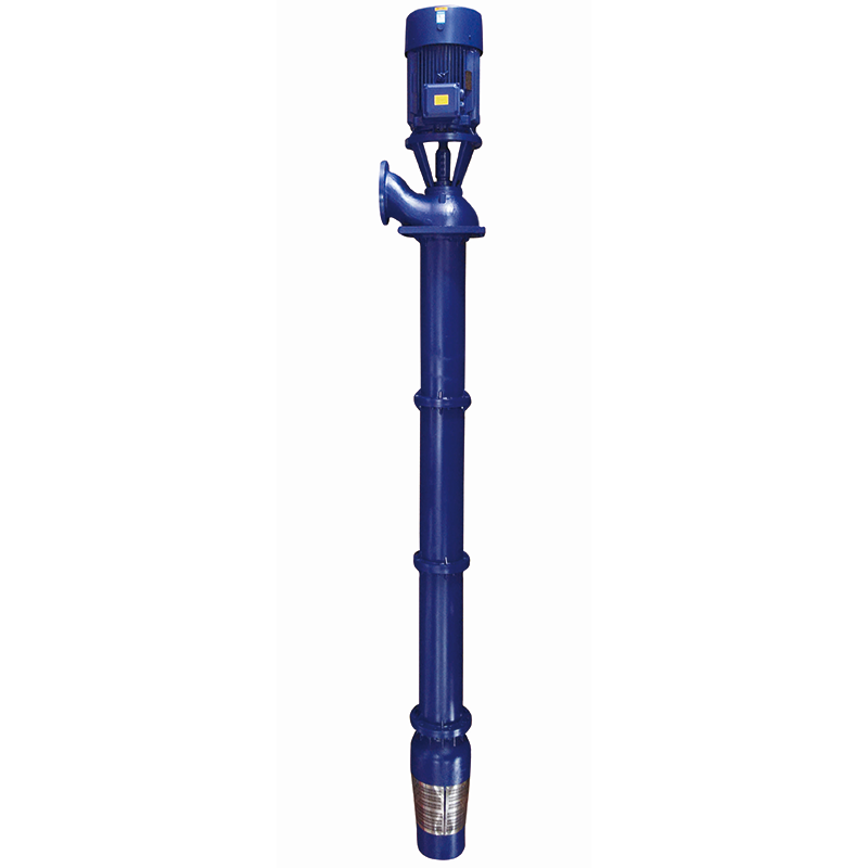
The LC Series Vertical Long-Shaft Deep Well Pump is a multistage deep-well water extraction equipment designed per national pump design and testing standards, featuring a wellhead-mounted motor with concentric long-shaft drive, modularly composed of centrifugal/mixed-flow impellers, diffuser casings, column pipes, drive shafts, and pump base, enabling stable high-flow high-head delivery.
Resolves four critical operational challenges in deep-well applications: submersible motor failure and maintenance difficulty in underwater environments, vibration and wear caused by misalignment in long-shaft transmission, suboptimal energy efficiency under high-flow high-head conditions, and extended installation/maintenance cycles due to low modularity.
Suitable for cooling water intake in thermal/hydropower plants, raw water transfer in municipal waterworks, agricultural deep-well irrigation, municipal pipeline boosting, industrial process water supply, and emergency fire protection applications requiring deep-well deployment, long-cycle operation, and high-reliability performance.
Extended Service Life: Bronze-base bearing support + 2Cr13/304 stainless steel transmission shaft resist wear & misalignment. Combined with G2.5 dynamically balanced impeller, design lifespan ≥20 years—over 35% longer than standard long-shaft deep-well pumps.
Significant Energy Savings: CFD-optimized hydraulic model + optional enclosed gearbox (transmission efficiency ≥95%) achieve ≥80% rated efficiency. Combined with wide high-efficiency range design, annual electricity costs drop by 20%–30%.
Lower Maintenance Costs: Integrated pump base + elevated motor bracket design enables mechanical seal replacement without disconnecting column pipes. Single technician completes core component maintenance within 2 hours, reducing labor costs by 50%.
Lightweight & Compact Design: Modular column pipes + lightweight transmission shaft assembly reduce overall weight by ~15% for equivalent head ratings, lowering wellhead load requirements & lifting complexity.
Faster Installation: Pre-aligned flanges + quick-install pump base enable vertical alignment & fixation on-site. Standard units reach commissioning readiness within 4 hours from positioning, compressing installation cycle by 40%.
Industrial Applications: Power plant cooling circulation, steel/metallurgy process water, mining drainage, chemical process water supply, supporting high-head, high-flow, continuous operation conditions.
Municipal Applications: Municipal waterworks deep-well intake, municipal network boosting, industrial park water supply integration, adapting to standard conditions: pH 6.5–8.5, H₂S ≤1.5 mg/L.
Agricultural Applications: Deep-well irrigation, farmland water conservancy, aquaculture water supply, supporting mobile/fixed deployment to meet seasonal peak water demand.
Emergency Applications: Fire backup systems, power-outage emergency water supply, off-grid independent water supply, achieving zero-delay response with diesel/dual-power control cabinets.
Media Compatibility: Non-corrosive clean water. Solid content ≤0.01% (by weight). pH 6.5–8.5, H₂S ≤1.5 mg/L, water temperature ≤40℃/104℉.
 Product Structure Diagram
 | No. | Material Name | Material |
| 1 | Electric Motor | Component | |
| 2 | Motor Support Bracket | QT400-18 | |
| 3 | Motor Coupling | HT200 | |
| 4 | Mechanical Seal Gland | QT400-18 | |
| 5 | Mechanical Seal | WC/SiC Mechanical Seal Faces | |
| 6 | Seal Positioning Ring | ZG235-450 | |
| 7 | Discharge Head | Q400-18 | |
| 8 | Shaft Sleeve | ZG235-450 | |
| 9 | Thrust Roller Bearing | Bearing Steel | |
| 10 | Bearing Housing | QT400-18 | |
| 11 | Pump Casing Support Bracket | QT400-18 | |
| 12 | Casing Support Bearing | Copper Alloy | |
| 13 | Drive Shaft Coupling | ZG235-450 | |
| 14 | Shaft | 20Cr13 | |
| 15 | Column Pipe Bearing | Copper Alloy | |
| 16 | Column Pipe Support Bracket | QT400-18 | |
| 17 | Upper Diffuser | HT200 | |
| 18 | Diffuser Bearing | Copper Alloy | |
| 19 | Tapered Adapter Sleeve | 20Cr13 | |
| 20 | Impeller | O6Cr19Ni10 | |
| 21 | Intermediate Diffuser | HT200 | |
| 22 | Suction Inlet Bearing | Copper Alloy | |
| 23 | Suction Inlet | HT200 | |
| 24 | Suction Strainer | O6Cr19Ni10 | |
| 25 | High-Pressure Thrust Bearing | Composite Material + Wear-Resistant Alloy Steel |
| Model | Number of Stages | Flow Rate | Head | Speed | Power | Efficiency | Downhole Pump Diameter | Column Pipe Diameter | Overall Dimensions | |
| TYPE | N | m³h | H | r/min | kw | % | mm | DN | H2 | H3 |
| 150LC5-7 | 4 | 5 | 28 | 2900 | 2.2 | 60 | 142 | 80 | 205 | 311 |
| 150LC5-7 | 5 | 5 | 35 | 2900 | 2.2 | 60 | 142 | 80 | 205 | 311 |
| 150LC5-7 | 6 | 5 | 42 | 2900 | 2.2 | 60 | 142 | 80 | 205 | 311 |
| 150LC5-7 | 7 | 5 | 49 | 2900 | 3 | 60 | 142 | 80 | 205 | 346 |
| 150LC5-7 | 8 | 5 | 56 | 2900 | 3 | 60 | 142 | 80 | 205 | 346 |
| 150LC5-7 | 9 | 5 | 63 | 2900 | 3 | 60 | 142 | 80 | 205 | 346 |
| 150LC5-7 | 10 | 5 | 70 | 2900 | 3 | 60 | 142 | 80 | 205 | 346 |
| 150LC5-7 | 11 | 5 | 77 | 2900 | 3 | 60 | 142 | 80 | 205 | 346 |
| 150LC5-7 | 12 | 5 | 84 | 2900 | 3 | 60 | 142 | 80 | 205 | 346 |
| 150LC5-7 | 13 | 5 | 91 | 2900 | 3 | 60 | 142 | 80 | 205 | 346 |
| 150LC5-7 | 14 | 5 | 98 | 2900 | 4 | 60 | 142 | 80 | 205 | 392 |
| 150LC5-7 | 15 | 5 | 105 | 2900 | 4 | 60 | 142 | 80 | 205 | 392 |
| 150LC5-7 | 16 | 5 | 112 | 2900 | 4 | 60 | 142 | 80 | 205 | 392 |
| 150LC5-7 | 17 | 5 | 119 | 2900 | 4 | 60 | 142 | 80 | 205 | 392 |
| 150LC5-7 | 18 | 5 | 126 | 2900 | 4 | 60 | 142 | 80 | 205 | 392 |
| 150LC5-7 | 19 | 5 | 133 | 2900 | 4 | 60 | 142 | 80 | 205 | 392 |
| 150LC5-7 | 20 | 5 | 140 | 2900 | 5.5 | 60 | 142 | 80 | 265 | 390 |
| 175LC10-15 | 1 | 10 | 15 | 2900 | 3 | 62 | 165 | 80 | 205 | 346 |
| 175LC10-15 | 2 | 10 | 30 | 2900 | 4 | 62 | 165 | 80 | 205 | 392 |
| 175LC10-15 | 3 | 10 | 45 | 2900 | 5.5 | 62 | 165 | 80 | 265 | 390 |
| 175LC10-15 | 4 | 10 | 60 | 2900 | 5.5 | 62 | 165 | 80 | 265 | 390 |
| 175LC10-15 | 5 | 10 | 75 | 2900 | 5.5 | 62 | 165 | 80 | 265 | 390 |
| 175LC10-15 | 6 | 10 | 90 | 2900 | 7.5 | 62 | 165 | 80 | 265 | 390 |
| 175LC10-15 | 7 | 10 | 105 | 2900 | 7.5 | 62 | 165 | 80 | 265 | 390 |
| 175LC10-15 | 8 | 10 | 120 | 2900 | 11 | 62 | 165 | 80 | 290 | 498 |
| 175LC10-15 | 9 | 10 | 135 | 2900 | 11 | 62 | 165 | 80 | 290 | 498 |
| 175LC10-15 | 10 | 10 | 150 | 2900 | 11 | 62 | 165 | 80 | 290 | 498 |
| 175LC10-15 | 11 | 10 | 165 | 2900 | 15 | 62 | 165 | 80 | 290 | 498 |
| 175LC10-15 | 12 | 10 | 180 | 2900 | 15 | 62 | 165 | 80 | 290 | 498 |
| 175LC10-15 | 13 | 10 | 195 | 2900 | 15 | 62 | 165 | 80 | 290 | 498 |
| 175LC10-15 | 14 | 10 | 210 | 2900 | 15 | 62 | 165 | 80 | 290 | 498 |
| 175LC10-15 | 15 | 10 | 225 | 2900 | 18.5 | 62 | 165 | 80 | 290 | 524 |
| Model | Number of Stages | Flow Rate | Head | Speed | Power | Efficiency | Downhole Pump Diameter | Column Pipe Diameter | Overall Dimensions | |
| TYPE | N | m³h | H | r/min | kw | % | mm | DN | H2 | H3 |
| 175LC10-15 | 16 | 10 | 240 | 2900 | 18.5 | 62 | 165 | 80 | 290 | 524 |
| 175LC20-13 | 2 | 20 | 26 | 2900 | 4 | 65 | 165 | 80 | 205 | 392 |
| 175LC20-13 | 3 | 20 | 39 | 2900 | 5.5 | 65 | 165 | 80 | 265 | 390 |
| 175LC20-13 | 4 | 20 | 52 | 2900 | 7.5 | 65 | 165 | 80 | 265 | 390 |
| 175LC20-13 | 5 | 20 | 65 | 2900 | 7.5 | 65 | 165 | 80 | 265 | 390 |
| 175LC20-13 | 6 | 20 | 78 | 2900 | 11 | 65 | 165 | 80 | 290 | 498 |
| 175LC20-13 | 7 | 20 | 91 | 2900 | 11 | 65 | 165 | 80 | 290 | 498 |
| 175LC20-13 | 8 | 20 | 104 | 2900 | 15 | 65 | 165 | 80 | 290 | 498 |
| 175LC20-13 | 9 | 20 | 117 | 2900 | 15 | 65 | 165 | 80 | 290 | 498 |
| 175LC20-13 | 10 | 20 | 130 | 2900 | 15 | 65 | 165 | 80 | 290 | 498 |
| 175LC20-13 | 11 | 20 | 143 | 2900 | 15 | 65 | 165 | 80 | 290 | 498 |
| 175LC20-13 | 12 | 20 | 156 | 2900 | 18.5 | 65 | 165 | 80 | 290 | 524 |
| 175LC20-13 | 13 | 20 | 169 | 2900 | 18.5 | 65 | 165 | 80 | 290 | 524 |
| 175LC20-13 | 14 | 20 | 182 | 2900 | 22 | 65 | 165 | 80 | 290 | 578 |
| 175LC20-13 | 15 | 20 | 195 | 2900 | 22 | 65 | 165 | 80 | 290 | 578 |
| 175LC20-13 | 16 | 20 | 208 | 2900 | 22 | 65 | 165 | 80 | 290 | 578 |
| 175LC20-13 | 17 | 20 | 221 | 2900 | 30 | 65 | 165 | 80 | 290 | 669 |
| 175LC20-13 | 18 | 20 | 234 | 2900 | 30 | 65 | 165 | 80 | 290 | 709 |
| 175LC20-13 | 19 | 20 | 247 | 2900 | 30 | 65 | 165 | 80 | 290 | 669 |
| 175LC20-13 | 20 | 20 | 260 | 2900 | 37 | 65 | 165 | 80 | 290 | 669 |
| 175LC32-12 | 2 | 32 | 24 | 2900 | 5.5 | 67 | 165 | 80 | 265 | 390 |
| 175LC32-12 | 3 | 32 | 36 | 2900 | 7.5 | 67 | 165 | 80 | 265 | 390 |
| 175LC32-12 | 4 | 32 | 48 | 2900 | 11 | 67 | 165 | 80 | 290 | 498 |
| 175LC32-12 | 5 | 32 | 60 | 2900 | 11 | 67 | 165 | 80 | 290 | 498 |
| 175LC32-12 | 6 | 32 | 72 | 2900 | 15 | 67 | 165 | 80 | 290 | 498 |
| 175LC32-12 | 7 | 32 | 84 | 2900 | 15 | 67 | 165 | 80 | 290 | 498 |
| 175LC32-12 | 8 | 32 | 96 | 2900 | 18.5 | 67 | 165 | 80 | 290 | 524 |
| 175LC32-12 | 9 | 32 | 108 | 2900 | 18.5 | 67 | 165 | 80 | 290 | 524 |
| 175LC32-12 | 10 | 32 | 120 | 2900 | 22 | 67 | 165 | 80 | 290 | 578 |
| 175LC32-12 | 11 | 32 | 132 | 2900 | 22 | 67 | 165 | 80 | 290 | 578 |
| 175LC32-12 | 12 | 32 | 144 | 2900 | 30 | 67 | 165 | 80 | 290 | 669 |
| 175LC32-12 | 13 | 32 | 156 | 2900 | 30 | 67 | 165 | 80 | 290 | 669 |
| Model | Number of Stages | Flow Rate | Head | Speed | Power | Efficiency | Downhole Pump Diameter | Column Pipe Diameter | Overall Dimensions | |
| TYPE | N | m³h | H | r/min | kw | % | mm | DN | H2 | H3 |
| 175LC32-12 | 14 | 32 | 168 | 2900 | 30 | 67 | 165 | 80 | 290 | 669 |
| 175LC32-12 | 15 | 32 | 180 | 2900 | 30 | 67 | 165 | 80 | 290 | 669 |
| 175LC32-12 | 16 | 32 | 192 | 2900 | 37 | 67 | 165 | 80 | 290 | 669 |
| 175LC32-12 | 17 | 32 | 204 | 2900 | 37 | 67 | 165 | 80 | 290 | 669 |
| 175LC32-12 | 18 | 32 | 216 | 2900 | 45 | 67 | 165 | 80 | 315 | 709 |
| 175LC32-12 | 19 | 32 | 228 | 2900 | 45 | 67 | 165 | 80 | 315 | 709 |
| 175LC32-12 | 20 | 32 | 240 | 2900 | 45 | 67 | 165 | 80 | 315 | 709 |
| 200LC50-13 | 2 | 50 | 26 | 2900 | 7.5 | 69 | 185 | 80 | 265 | 390 |
| 200LC50-13 | 3 | 50 | 39 | 2900 | 11 | 69 | 185 | 80 | 290 | 498 |
| 200LC50-13 | 4 | 50 | 52 | 2900 | 15 | 69 | 185 | 80 | 290 | 498 |
| 200LC50-13 | 5 | 50 | 65 | 2900 | 18.5 | 69 | 185 | 80 | 290 | 524 |
| 200LC50-13 | 6 | 50 | 78 | 2900 | 18.5 | 69 | 185 | 80 | 290 | 524 |
| 200LC50-13 | 7 | 50 | 91 | 2900 | 22 | 69 | 185 | 80 | 290 | 578 |
| 200LC50-13 | 8 | 50 | 104 | 2900 | 30 | 69 | 185 | 80 | 290 | 669 |
| 200LC50-13 | 9 | 50 | 117 | 2900 | 30 | 69 | 185 | 80 | 290 | 669 |
| 200LC50-13 | 10 | 50 | 130 | 2900 | 30 | 69 | 185 | 80 | 290 | 669 |
| 200LC50-13 | 11 | 50 | 143 | 2900 | 37 | 69 | 185 | 80 | 290 | 669 |
| 200LC50-13 | 12 | 50 | 156 | 2900 | 37 | 69 | 185 | 80 | 290 | 669 |
| 200LC50-13 | 13 | 50 | 169 | 2900 | 37 | 69 | 185 | 80 | 290 | 669 |
| 200LC50-13 | 14 | 50 | 182 | 2900 | 45 | 69 | 185 | 80 | 315 | 709 |
| 200LC50-13 | 15 | 50 | 195 | 2900 | 45 | 69 | 185 | 80 | 315 | 709 |
| 200LC50-13 | 16 | 50 | 208 | 2900 | 55 | 69 | 185 | 80 | 345 | 770 |
| 200LC50-13 | 17 | 50 | 221 | 2900 | 55 | 69 | 185 | 80 | 345 | 770 |
| 200LC50-13 | 18 | 50 | 234 | 2900 | 55 | 69 | 185 | 80 | 345 | 770 |
| 200LC50-13 | 19 | 50 | 247 | 2900 | 75 | 69 | 185 | 80 | 345 | 842 |
| 200LC50-13 | 20 | 50 | 260 | 2900 | 75 | 69 | 185 | 80 | 345 | 842 |
| 200LC80-18 | 2 | 80 | 36 | 2900 | 15 | 72 | 185 | 100 | 290 | 498 |
| 200LC80-18 | 3 | 80 | 54 | 2900 | 22 | 72 | 185 | 100 | 290 | 578 |
| 200LC80-18 | 4 | 80 | 72 | 2900 | 30 | 72 | 185 | 100 | 290 | 669 |
| 200LC80-18 | 5 | 80 | 90 | 2900 | 30 | 72 | 185 | 100 | 290 | 669 |
| 200LC80-18 | 6 | 80 | 108 | 2900 | 37 | 72 | 185 | 100 | 290 | 669 |
| 200LC80-18 | 7 | 80 | 126 | 2900 | 45 | 72 | 185 | 100 | 315 | 709 |
| Model | Number of Stages | Flow Rate | Head | Speed | Power | Efficiency | Downhole Pump Diameter | Column Pipe Diameter | Overall Dimensions | |
| TYPE | N | m³h | H | r/min | kw | % | mm | DN | H2 | H3 |
| 200LC80-18 | 8 | 80 | 144 | 2900 | 55 | 72 | 185 | 100 | 345 | 770 |
| 200LC80-18 | 9 | 80 | 162 | 2900 | 75 | 72 | 185 | 100 | 345 | 842 |
| 200LC80-18 | 10 | 80 | 180 | 2900 | 75 | 72 | 185 | 100 | 345 | 842 |
| 200LC80-18 | 11 | 80 | 198 | 2900 | 90 | 72 | 185 | 100 | 345 | 892 |
| 200LC80-18 | 12 | 80 | 216 | 2900 | 90 | 72 | 185 | 100 | 345 | 892 |
| 200LC80-18 | 13 | 80 | 234 | 2900 | 110 | 72 | 185 | 100 | 345 | 1054 |
| 250LC100-18 | 2 | 100 | 36 | 2900 | 18.5 | 73 | 235 | 100 | 290 | 524 |
| 250LC100-18 | 3 | 100 | 54 | 2900 | 30 | 73 | 235 | 100 | 290 | 669 |
| 250LC100-18 | 4 | 100 | 72 | 2900 | 37 | 73 | 235 | 100 | 290 | 669 |
| 250LC100-18 | 5 | 100 | 90 | 2900 | 45 | 73 | 235 | 100 | 315 | 709 |
| 250LC100-18 | 6 | 100 | 108 | 2900 | 45 | 73 | 235 | 100 | 315 | 709 |
| 250LC100-18 | 7 | 100 | 126 | 2900 | 55 | 73 | 235 | 100 | 345 | 770 |
| 250LC100-18 | 8 | 100 | 144 | 2900 | 75 | 73 | 235 | 100 | 345 | 842 |
| 250LC100-18 | 9 | 100 | 162 | 2900 | 75 | 73 | 235 | 100 | 345 | 842 |
| 250LC100-18 | 10 | 100 | 180 | 2900 | 90 | 73 | 235 | 100 | 345 | 892 |
| 250LC100-18 | 11 | 100 | 198 | 2900 | 90 | 73 | 235 | 100 | 345 | 892 |
| 250LC100-18 | 12 | 100 | 216 | 2900 | 110 | 73 | 235 | 100 | 345 | 1054 |
| 250LC100-18 | 13 | 100 | 234 | 2900 | 132 | 73 | 235 | 100 | 345 | 1164 |
| 250LC130-8.5 | 4 | 130 | 34 | 1450 | 18.5 | 75 | 242 | 125 | 295 | 578 |
| 250LC130-8.5 | 5 | 130 | 42.5 | 1450 | 22 | 75 | 242 | 125 | 295 | 616 |
| 250LC130-8.5 | 6 | 130 | 51 | 1450 | 30 | 75 | 242 | 125 | 320 | 669 |
| 250LC130-8.5 | 7 | 130 | 59.5 | 1450 | 37 | 75 | 242 | 125 | 320 | 684 |
| 250LC130-8.5 | 8 | 130 | 68 | 1450 | 37 | 75 | 242 | 125 | 320 | 684 |
| 250LC130-8.5 | 9 | 130 | 76.5 | 1450 | 45 | 75 | 242 | 125 | 320 | 709 |
| 250LC130-8.5 | 10 | 130 | 85 | 1450 | 45 | 75 | 242 | 125 | 320 | 709 |
| 250LC130-8.5 | 11 | 130 | 93.5 | 1450 | 55 | 75 | 242 | 125 | 345 | 770 |
| 250LC130-8.5 | 12 | 130 | 102 | 1450 | 55 | 75 | 242 | 125 | 345 | 770 |
| 250LC130-8.5 | 13 | 130 | 110.5 | 1450 | 75 | 75 | 242 | 125 | 345 | 842 |
| 300LC160-11.5 | 3 | 160 | 34.5 | 1450 | 22 | 78 | 295 | 150 | 295 | 616 |
| 300LC160-11.5 | 4 | 160 | 46 | 1450 | 30 | 78 | 295 | 150 | 320 | 669 |
| 300LC160-11.5 | 5 | 160 | 57.5 | 1450 | 37 | 78 | 295 | 150 | 320 | 684 |
| 300LC160-11.5 | 6 | 160 | 69 | 1450 | 45 | 78 | 295 | 150 | 320 | 709 |
| Model | Number of Stages | Flow Rate | Head | Speed | Power | Efficiency | Downhole Pump Diameter | Column Pipe Diameter | Overall Dimensions | |
| TYPE | N | m³h | H | r/min | kw | % | mm | DN | H2 | H3 |
| 300LC160-11.5 | 7 | 160 | 80.5 | 1450 | 55 | 78 | 295 | 150 | 345 | 770 |
| 300LC160-11.5 | 8 | 160 | 92 | 1450 | 75 | 78 | 295 | 150 | 345 | 842 |
| 300LC160-11.5 | 9 | 160 | 103.5 | 1450 | 75 | 78 | 295 | 150 | 345 | 842 |
| 300LC160-11.5 | 10 | 160 | 115 | 1450 | 75 | 78 | 295 | 150 | 345 | 842 |
| 300LC160-11.5 | 11 | 160 | 126.5 | 1450 | 90 | 78 | 295 | 150 | 345 | 893 |
| 300LC160-11.5 | 12 | 160 | 138 | 1450 | 90 | 78 | 295 | 150 | 345 | 893 |
| 300LC220-13.5 | 2 | 220 | 27 | 1450 | 22 | 79 | 295 | 150 | 295 | 616 |
| 300LC220-13.5 | 3 | 220 | 40.5 | 1450 | 37 | 79 | 295 | 150 | 320 | 684 |
| 300LC220-13.5 | 4 | 220 | 54 | 1450 | 45 | 79 | 295 | 150 | 320 | 709 |
| 300LC220-13.5 | 5 | 220 | 67.5 | 1450 | 55 | 79 | 295 | 150 | 345 | 770 |
| 300LC220-13.5 | 6 | 220 | 81 | 1450 | 75 | 79 | 295 | 150 | 345 | 842 |
| 300LC220-13.5 | 7 | 220 | 94.5 | 1450 | 90 | 79 | 295 | 150 | 345 | 893 |
| 300LC220-13.5 | 8 | 220 | 108 | 1450 | 90 | 79 | 295 | 150 | 345 | 893 |
| 300LC220-13.5 | 9 | 220 | 121.5 | 1450 | 110 | 79 | 295 | 150 | 345 | 1054 |
| 350LC300-15 | 2 | 300 | 30 | 1450 | 37 | 80 | 346 | 200 | 320 | 684 |
| 350LC300-15 | 3 | 300 | 45 | 1450 | 55 | 80 | 346 | 200 | 345 | 770 |
| 350LC300-15 | 4 | 300 | 60 | 1450 | 75 | 80 | 346 | 200 | 345 | 842 |
| 350LC300-15 | 5 | 300 | 75 | 1450 | 90 | 80 | 346 | 200 | 345 | 893 |
| 350LC300-15 | 6 | 300 | 90 | 1450 | 110 | 80 | 346 | 200 | 345 | 1054 |
| 350LC300-15 | 7 | 300 | 105 | 1450 | 132 | 80 | 346 | 200 | 345 | 1164 |
| 350LC300-15 | 8 | 300 | 120 | 1450 | 160 | 80 | 346 | 200 | 345 | 1164 |
| 400LC400-18 | 1 | 400 | 18 | 1450 | 37 | 78 | 430 | 200 | 320 | 684 |
| 400LC400-18 | 2 | 400 | 36 | 1450 | 75 | 78 | 430 | 200 | 345 | 842 |
| 400LC400-18 | 3 | 400 | 54 | 1450 | 90 | 78 | 430 | 200 | 345 | 893 |
| 400LC400-18 | 4 | 400 | 72 | 1450 | 132 | 78 | 430 | 200 | 345 | 1164 |
| 400LC400-18 | 5 | 400 | 90 | 1450 | 160 | 78 | 430 | 200 | 345 | 1164 |
| 400LC400-18 | 6 | 400 | 108 | 1450 | 200 | 78 | 430 | 200 | 345 | 1164 |
| 400LC400-18 | 7 | 400 | 126 | 1450 | 220 | 78 | 430 | 200 | 450 | 1346 |
| 400LC400-18 | 8 | 400 | 144 | 1450 | 250 | 78 | 430 | 200 | 450 | 1346 |
| 400LC400-18 | 9 | 400 | 162 | 1450 | 280 | 78 | 430 | 200 | 450 | 1346 |
| 400LC500-16 | 1 | 500 | 16 | 1450 | 37 | 78 | 430 | 200 | 320 | 684 |
| 400LC500-16 | 2 | 500 | 32 | 1450 | 75 | 78 | 430 | 200 | 345 | 842 |
| Model | Number of Stages | Flow Rate | Head | Speed | Power | Efficiency | Downhole Pump Diameter | Column Pipe Diameter | Overall Dimensions | |
| TYPE | N | m³h | H | r/min | kw | % | mm | DN | H2 | H3 |
| 400LC500-16 | 3 | 500 | 48 | 1450 | 90 | 78 | 430 | 200 | 345 | 893 |
| 400LC500-16 | 4 | 500 | 64 | 1450 | 132 | 78 | 430 | 200 | 345 | 1164 |
| 400LC500-16 | 5 | 500 | 80 | 1450 | 160 | 78 | 430 | 200 | 345 | 1164 |
| 400LC500-16 | 6 | 500 | 96 | 1450 | 200 | 78 | 430 | 200 | 345 | 1164 |
| 400LC500-16 | 7 | 500 | 112 | 1450 | 220 | 78 | 430 | 200 | 450 | 1346 |
| 400LC500-16 | 8 | 500 | 128 | 1450 | 250 | 78 | 430 | 200 | 450 | 1346 |
| 400LC500-16 | 9 | 500 | 144 | 1450 | 280 | 78 | 430 | 200 | 450 | 1346 |
| 400LC500-16 | 10 | 500 | 160 | 1450 | 315 | 78 | 430 | 200 | 450 | 1346 |
| 400LC600-14 | 1 | 600 | 14 | 1450 | 37 | 78 | 430 | 250 | 320 | 684 |
| 400LC600-14 | 2 | 600 | 28 | 1450 | 75 | 78 | 430 | 250 | 345 | 842 |
| 400LC600-14 | 3 | 600 | 42 | 1450 | 90 | 78 | 430 | 250 | 345 | 893 |
| 400LC600-14 | 4 | 600 | 56 | 1450 | 132 | 78 | 430 | 250 | 345 | 1164 |
| 400LC600-14 | 5 | 600 | 70 | 1450 | 160 | 78 | 430 | 250 | 345 | 1164 |
| 400LC600-14 | 6 | 600 | 84 | 1450 | 200 | 78 | 430 | 250 | 345 | 1164 |
| 400LC600-14 | 7 | 600 | 98 | 1450 | 220 | 78 | 430 | 250 | 450 | 1346 |
| 400LC600-14 | 8 | 600 | 112 | 1450 | 250 | 78 | 430 | 250 | 450 | 1346 |
| 400LC600-14 | 9 | 600 | 126 | 1450 | 280 | 78 | 430 | 250 | 450 | 1346 |
| 400LC600-14 | 10 | 600 | 140 | 1450 | 315 | 78 | 430 | 250 | 450 | 1346 |
| 500LC700-21 | 1 | 700 | 21 | 1450 | 75 | 78 | 540 | 300 | 345 | 842 |
| 500LC700-21 | 2 | 700 | 42 | 1450 | 160 | 78 | 540 | 300 | 345 | 1164 |
| 500LC700-21 | 3 | 700 | 63 | 1450 | 220 | 78 | 540 | 300 | 450 | 1346 |
| 500LC700-21 | 4 | 700 | 84 | 1450 | 280 | 78 | 540 | 300 | 450 | 1346 |
| 500LC700-21 | 5 | 700 | 105 | 1450 | 355 | 78 | 540 | 300 | 450 | 1346 |
| 500LC800-20 | 1 | 800 | 20 | 1450 | 75 | 78 | 540 | 300 | 345 | 842 |
| 500LC800-20 | 2 | 800 | 40 | 1450 | 160 | 78 | 540 | 300 | 345 | 1164 |
| 500LC800-20 | 3 | 800 | 60 | 1450 | 220 | 78 | 540 | 300 | 450 | 1346 |
| 500LC800-20 | 4 | 800 | 80 | 1450 | 280 | 78 | 540 | 300 | 450 | 1346 |
| 500LC800-20 | 5 | 800 | 100 | 1450 | 355 | 78 | 540 | 300 | 450 | 1346 |
| 500LC1000-18 | 1 | 1000 | 18 | 1450 | 75 | 78 | 540 | 300 | 345 | 842 |
| 500LC1000-18 | 2 | 1000 | 36 | 1450 | 160 | 78 | 540 | 300 | 345 | 1164 |
| 500LC1000-18 | 3 | 1000 | 54 | 1450 | 220 | 78 | 540 | 300 | 450 | 1346 |
| 500LC1000-18 | 4 | 1000 | 72 | 1450 | 280 | 78 | 540 | 300 | 450 | 1346 |
| 500LC1000-18 | 5 | 1000 | 90 | 1450 | 355 | 78 | 540 | 300 | 450 | 1346 |
Media Requirements:
Media type: Non-corrosive clean water
Solid content: ≤0.01% (by weight)
Water quality: pH 6.5–8.5; H₂S ≤1.5 mg/L
Temperature Limits:
Media/Ambient temperature: Both ≤40°C (≤104°F)
System Limits:
Max. head: ≤300 m (subject to configuration)
Well conditions: Vertical wellbore; bi-directional deflection ≤1°
Installation Requirements:
Mounting: Vertical wellhead installation with horizontally fixed pump base
Drive mode: Long-shaft concentric direct drive (enclosed gearbox optional)
Custom Solutions: For special conditions (high temperature / strong corrosion / high sand content / ultra-deep wells), consult our engineering team before selection. Tailored pump solutions available.
National Standard Compliance: Strictly manufactured per GB/T 2816-2014 “Submersible pumps for wells” & JB/T 3564-2015 “Long-shaft deep-well pumps”. Hydraulic performance & mechanical safety 100% compliant. Third-party full performance curve test reports available.
Material & Environmental Certification: Wetted parts comply with RoHS/REACH directives. Stainless steel materials supplied with GB/T 3280/ASTM A240 certificates, ensuring zero heavy metal leaching risk.
International Quality System: ISO 9001:2015 certified. Core pressure-bearing components evaluated per CE/PED 2014/68/EU, meeting EU/US market entry requirements.
Factory Inspection Standard: Every unit undergoes 1.5× rated pressure hydrostatic test (5-min hold) + long-shaft concentricity calibration (radial runout ≤0.15 mm) + G2.5 dynamic balance calibration, guaranteeing zero-vibration, zero-leakage delivery.
Fast Standard Delivery: Covers flow 50–2000 m³/h, head 30–300 m. Standard ductile iron/2Cr13 stainless steel + bronze-base bearings. Technical confirmation & sample prototyping within 72 hours.
Deep Customization Capabilities:
Material Upgrade: Wetted parts optional in 304/316/duplex 2205 stainless steel for high-chloride, mild acid/alkali, or seawater desalination pretreatment conditions.
Transmission System: Optional oil-lubricated enclosed gearbox, universal joint coupling, sand-resistant bearing assembly for sandy water or ultra-deep well (>200 m) conditions.
Structural Adaptation: Custom column pipe length, pump base flange standard switching (GB/ANSI/DIN), wellhead reinforcement brackets, rain-proof/anti-corrosion coating customization.
Intelligent Expansion: Pre-wired interfaces for pressure/flow/vibration sensors; supports integration with VFD cabinets, IoT remote monitoring, multi-pump rotation modules.
Please contact us for customization inquiries. Our engineering team delivers process proposals within 48 hours.
Installation Key Points:
1.Fix pump base horizontally on wellhead foundation. Tighten anchor bolts symmetrically. Ensure pump shaft verticality ≤0.5 mm/m to prevent long-shaft misalignment wear.
2.Connect column pipes via flanges. Install one pipe clamp per 10 m to ensure uniform axial load distribution. Never transmit pipe stress to pump body.
3.Use pre-aligned couplings for transmission shaft connection. Tighten bolts symmetrically per torque requirements. Manually rotate shaft 3 turns after initial installation to confirm no binding.
4.Motor junction box faces outward. Secure cable along well wall. Grounding resistance ≤4 Ω. Prime pump before initial startup. Jog test to verify rotation (clockwise from motor end).
Commissioning Process: Prime & vent → Jog test for direction → No-load run 10 min → Slowly open discharge valve to rated duty → Record current/pressure/vibration/bearing temp data → Acceptance.
Request the “LC Long-Shaft Deep-Well Pump Installation & Maintenance Manual” (PDF/English version) for complete dimensional drawings, column pipe connection specs, and commissioning logs.
Q1: How does long-shaft concentric transmission prevent bearing misalignment wear from radial runout?
Uses bronze-base self-lubricating bearings + support guide bearings every 6–8 m. Combined with G2.5 balanced impeller & pre-aligned coupling, tested radial runout ≤0.15 mm, bearing lifespan ≥20,000 hours.
Q2: How does maintenance-free design enable “mechanical seal replacement without disconnecting column pipes”?
Integrated pump base + elevated motor bracket design. After loosening pump base bolts, rotor assembly can be lifted 300–500 mm as a unit, fully exposing mechanical seals for replacement without disconnecting column pipes.
Q3: How to protect transmission system in sandy water (solids ≤0.01%)?
Standard bronze-base bearings + sand-resistant shaft sleeves. Optional tungsten carbide shaft sleeves + enclosed oil-lubricated gearbox. Tested: transmission efficiency decay ≤2%/year in 0.01% sand content, extending lifespan 3×.
Q4: What structural reinforcements are needed for ultra-deep wells (>200 m)?
Recommendations: ① Upgrade transmission shaft to 304 stainless steel + add guide bearings every 4–6 m; ② Increase column pipe wall thickness by 10%–15%; ③ Reinforce wellhead foundation + add anti-sway brackets. Provide well depth for custom evaluation.
Q5: How does enclosed gearbox achieve ≥95% transmission efficiency with fast heat dissipation?
Uses spiral bevel gears + forced oil circulation lubrication. Gear meshing precision reaches ISO 1328-1 Grade 6. Combined with external heat sink design, tested full-load efficiency ≥95%, temperature rise ≤35 K.