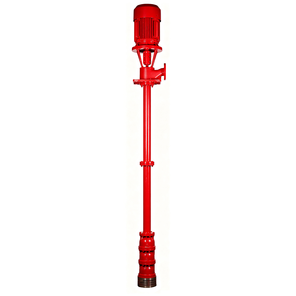
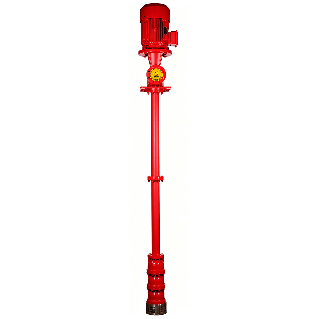
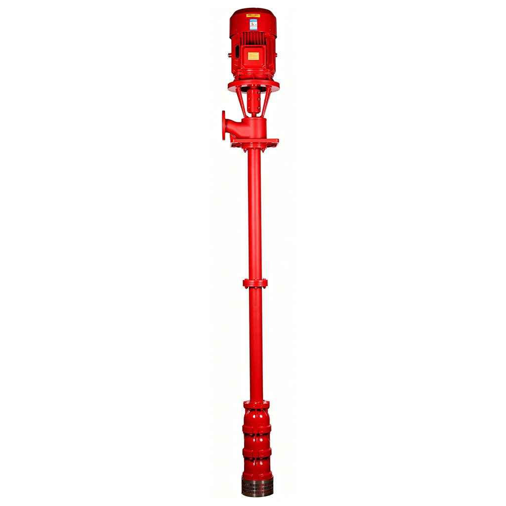
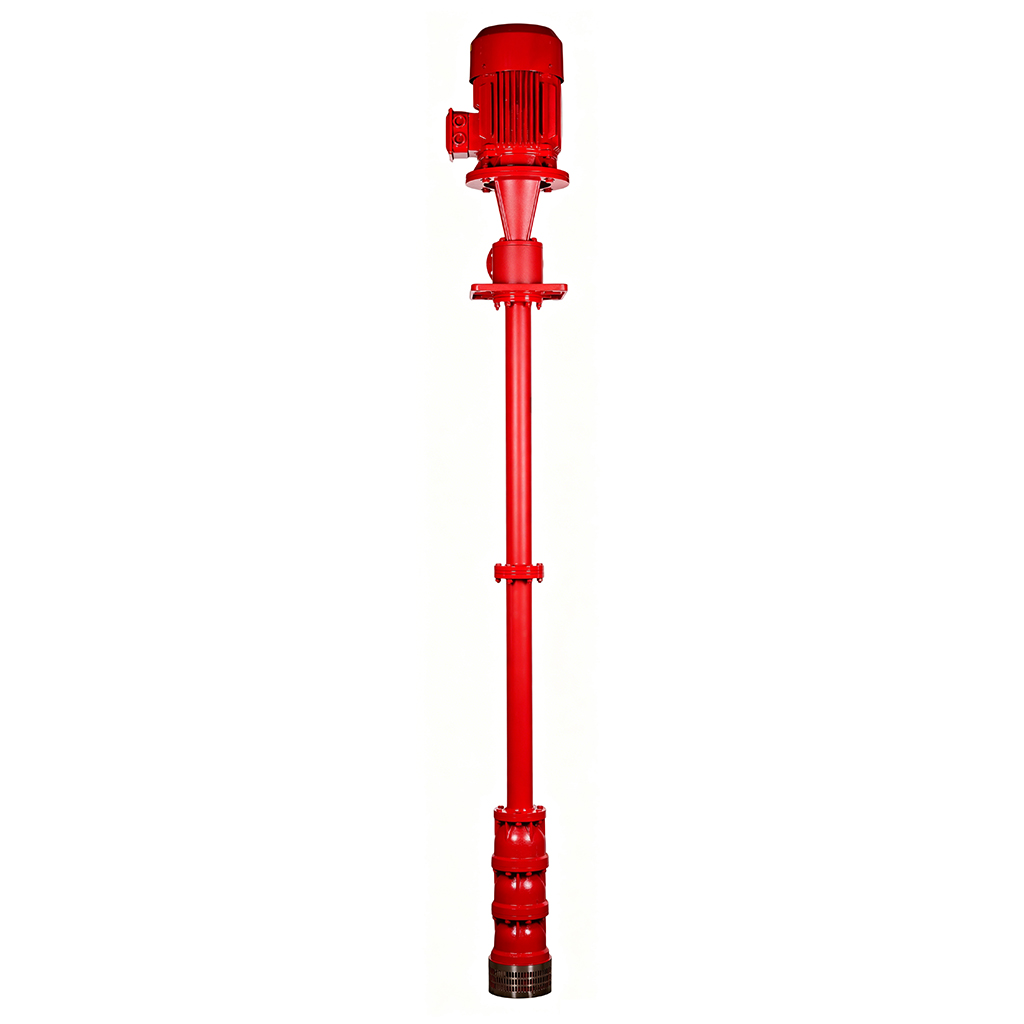
The Deep Well Fire Pump Set is a firefighting water supply unit manufactured in compliance with China’s GB 6245-2006 standard for fire pump performance.
It ensures stable water extraction from deep wells to meet the pressure and flow requirements of fire protection systems.
Suitable for high-rise buildings, industrial parks, rural fire protection, and emergency backup water sources in regions with accessible groundwater.
Extended Service Life: Impellers crafted from 06Cr19Ni10 stainless steel + shafts made of quenched & tempered 20Cr13, paired with tungsten carbide vs. silicon carbide mechanical seals, improving wear/corrosion resistance by 50%. Design lifespan ≥15 years—over 35% longer than standard cast-iron deep-well fire pumps.
Energy-Efficient Operation: Vertical multi-stage centrifugal structure + optimized hydraulic model achieves ≥78% efficiency at rated duty point. Combined with VFD control for on-demand water supply, reducing comprehensive energy consumption by 20%–35% vs. traditional solutions.
Lower Maintenance Costs: Surface-mounted motor and pump base design enables routine inspection, bearing lubrication, and seal replacement without well entry. One technician completes standard maintenance within 30 minutes, reducing labor costs by 60%.
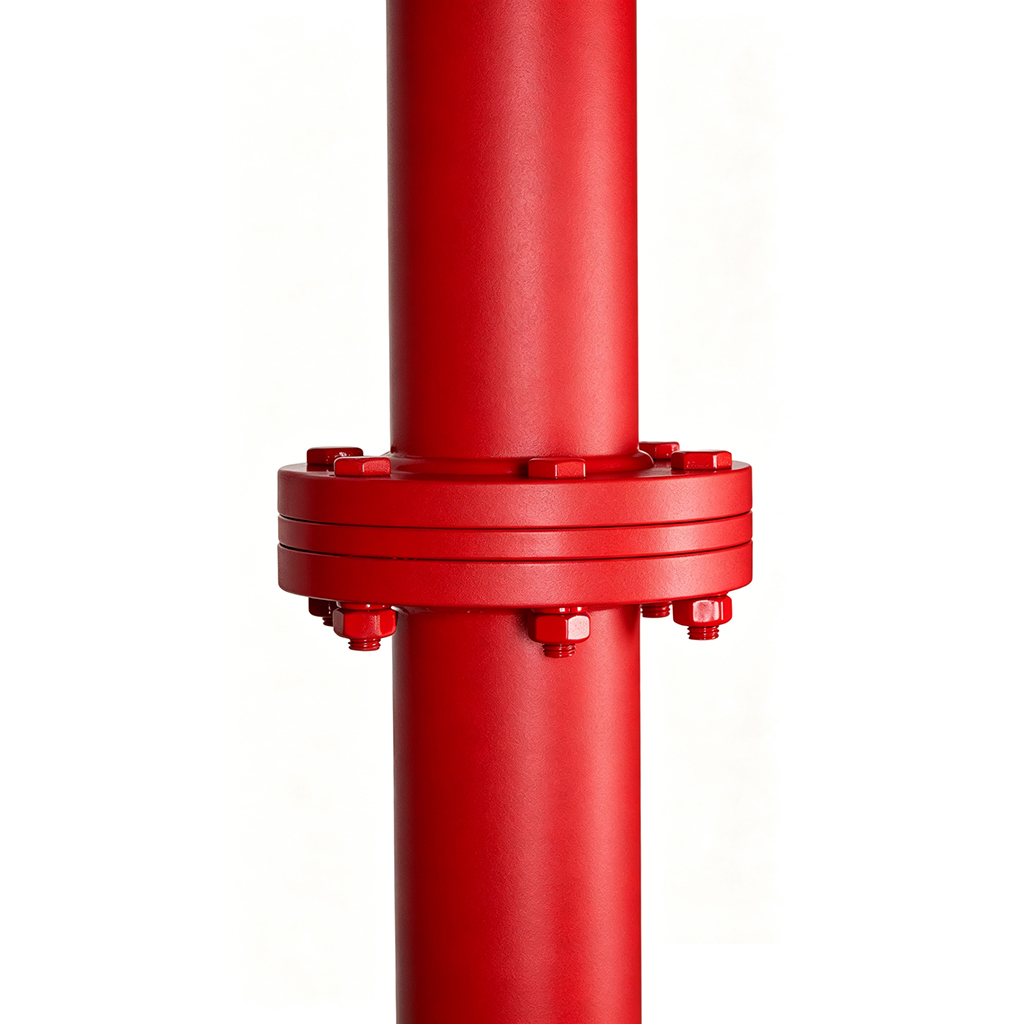
Lightweight & Compact Design: High-strength column pipes + modular impeller assembly reduce overall weight by ~15% for equivalent head ratings, lowering wellhead load requirements and lifting complexity.
Faster Installation: Pre-assembled diffuser shells + quick-connect flange interfaces allow vertical alignment and fixation on-site. Standard models reach commissioning readiness within 4–6 hours from unboxing—40% faster than traditional deep-well fire pump installation.
Core Fire Protection: Fire pipeline networks in industrial enterprises, temporary fire systems for construction projects, hydrant boosting for high-rise buildings, pressure stabilization for automatic sprinkler systems.
Media Compatibility: Clear water or liquids with similar physicochemical properties, free of solid particles (solid content ≤0.01% by weight, pH 6.5–8.5, H₂S ≤1.5 mg/L, media temperature ≤40℃/104℉).
Extended Applications: Boosting for domestic/industrial shared water systems, deep-well water extraction for municipal drainage, high-head agricultural irrigation, emergency backup for mine dewatering.
Special Condition Support: Compatible with vertical well depths ≤200m; optional accessories include sand filters, check valves, and pressure tanks to meet complex well conditions and system integration requirements.

|
| NO. | Component Name | Materials |
| 1 | Motor | Component | |
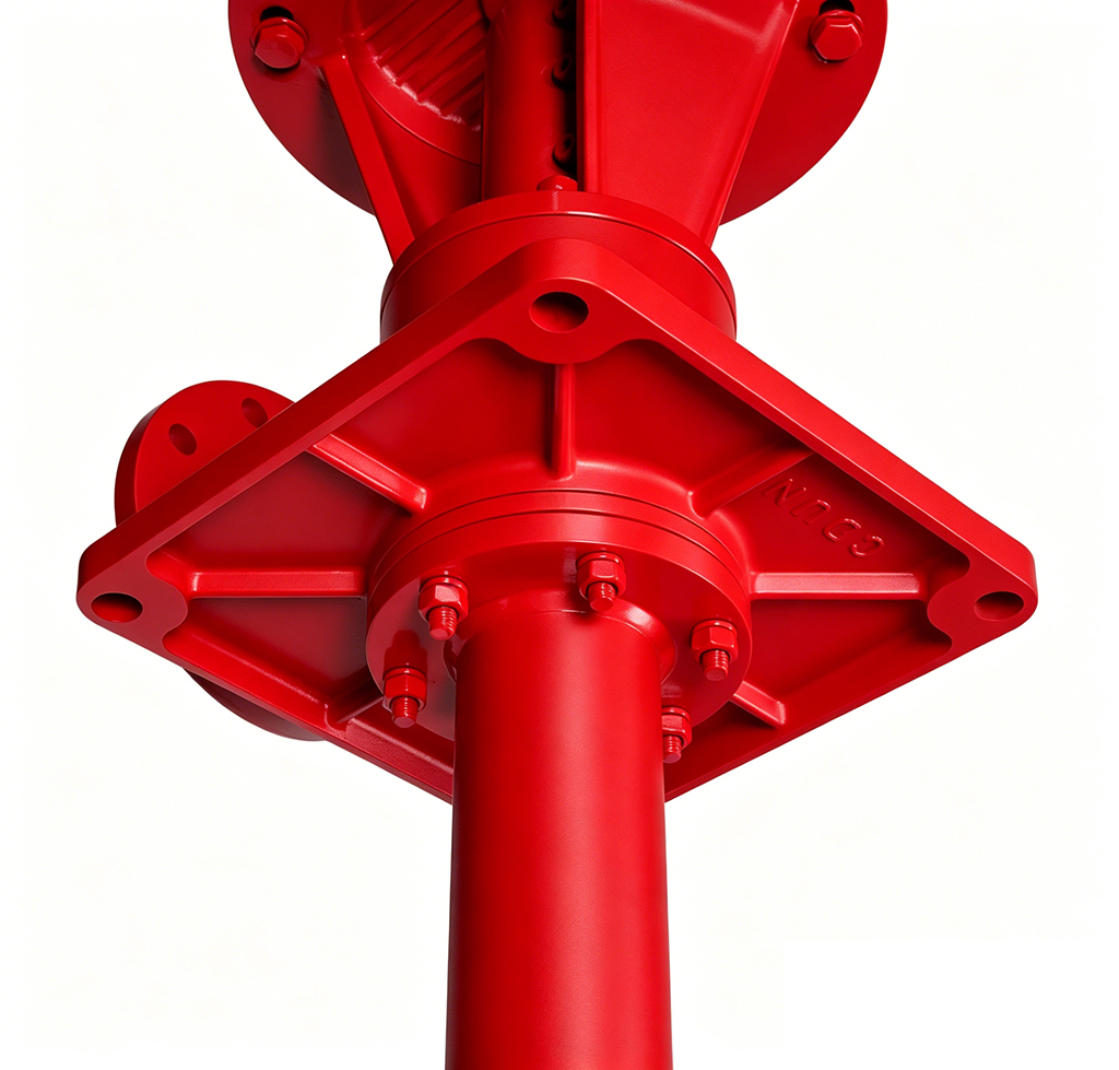
| 2 | Motor Bracket | QT400-18 | |
| 3 | Motor Coupling | ZG235-450 | |
| 4 | Mechanical Seal Gland | QT400-18 | |
| 5 | Mechanical Seal | WC/SiC Seal Pair | |
| 6 | Seal Positioning Ring | ZG235-450 | |
| 7 | Discharge End | QT400-18 | |
| 8 | Pump Body Support Bracket | QT400-18 | |
| 9 | Pump Body Support Bearing | Asbestos-Iron Bushing | |
| 10 | Drive Shaft Coupling | ZG235-450 | |
| 11 | Shaft | 20Cr13 | |
| 12 | Column Pipe Support Bearing | Asbestos-Iron Bushing | |
| 13 | Column Pipe Support Bracket | QT400-18 | |
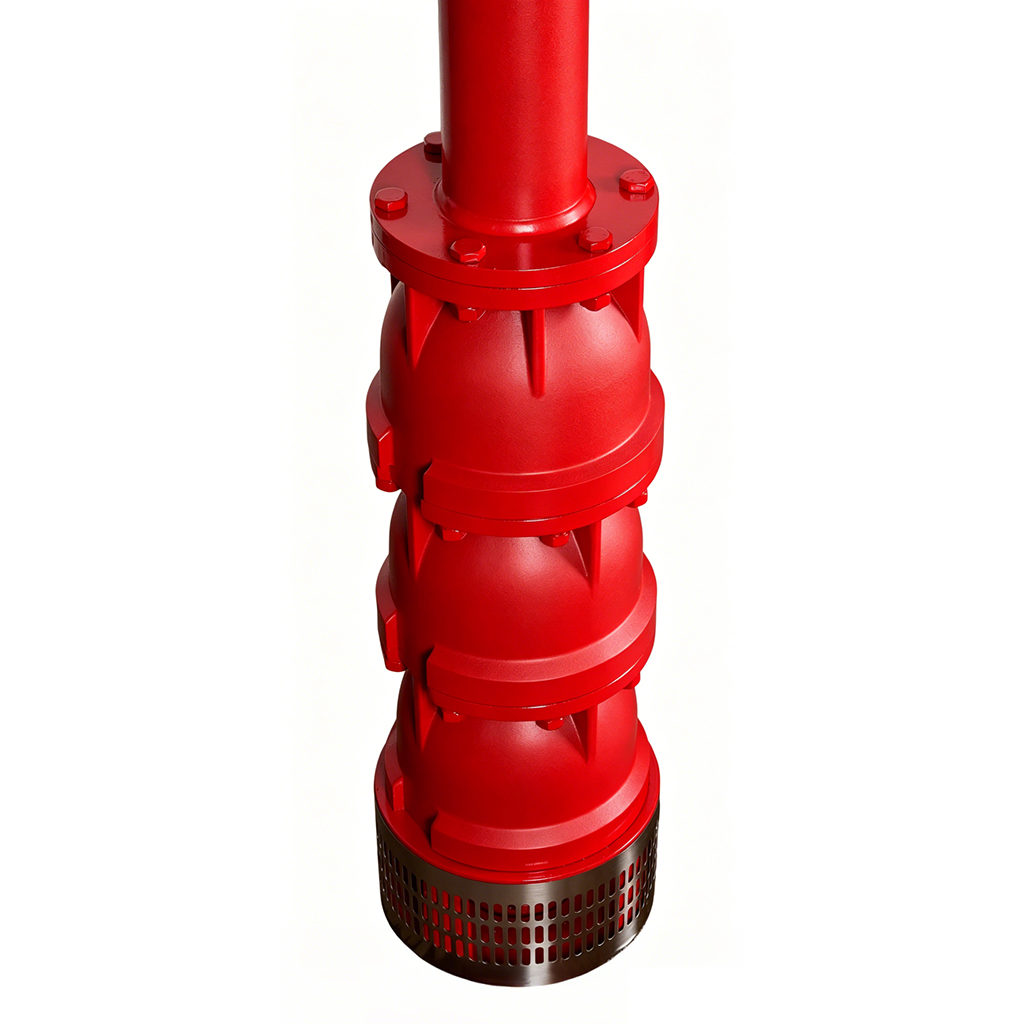
| 14 | Upper Diffuser | QT400-18 | |
| 15 | Diffuser Bearing | Rubber | |
| 16 | Tapered Sleeve | 20Cr13 | |
| 17 | Impeller | 06Cr19Ni10 | |
| 18 | Intermediate Diffuser | QT400-18 | |
| 19 | Suction Section Bearing | Rubber | |
| 20 | Suction Section | QT400-18 | |
| 21 | Filter Screen | 06Cr19Ni10 | |
| 22 | Thrust Disc | 20Cr13 | |
| 23 | Thrust Washer | PTFE Composite |
Performance Parameters Table
| No. | Fire Pump Model | Flow Rate (L/s) | Head (m) | Power (kW) | Speed (r/min) | Outlet Diameter | Maximum Working Pressure | Pressure at 150% Rated Flow |
| 61 | XBD14.4/10GJ-CD | 10 | 144 | 30 | 2900 | 80 | 2.016 | 0.936 |
| 62 | XBD15.6/10GJ-CD | 156 | 30 | 2900 | 2.184 | 1.014 | ||
| 63 | XBD17.0/10GJ-CD | 170 | 37 | 2900 | 2.380 | 1.105 | ||
| 64 | XBD18.0/10GJ-CD | 180 | 37 | 2900 | 2.520 | 1.170 | ||
| 65 | XBD3.6/15GJ-CD | 15 | 36 | 11 | 2900 | 80 | 0.504 | 0.234 |
| 66 | XBD4.0/15GJ-CD | 40 | 11 | 2900 | 0.560 | 0.260 | ||
| 67 | XBD5.0/15GJ-CD | 50 | 15 | 2900 | 0.700 | 0.325 | ||
| 68 | XBD6.0/15GJ-CD | 60 | 15 | 2900 | 0.840 | 0.390 | ||
| 69 | XBD7.2/15GJ-CD | 72 | 18.5 | 2900 | 1.008 | 0.468 | ||
| 70 | XBD8.4/15GJ-CD | 84 | 22 | 2900 | 1.176 | 0.546 | ||
| 71 | XBD9.6/15GJ-CD | 96 | 22 | 2900 | 1.344 | 0.624 | ||
| 72 | XBD10.0/15GJ-CD | 100 | 22 | 2900 | 1.400 | 0.650 | ||
| 73 | XBD11.0/15GJ-CD | 110 | 30 | 2900 | 1.540 | 0.715 | ||
| 74 | XBD12.0/15GJ-CD | 120 | 30 | 2900 | 1.680 | 0.780 | ||
| 75 | XBD13.0/15GJ-CD | 130 | 37 | 2900 | 1.820 | 0.845 | ||
| 76 | XBD14.0/15GJ-CD | 140 | 37 | 2900 | 1.960 | 0.910 | ||
| 77 | XBD15.6/15GJ-CD | 156 | 37 | 2900 | 2.184 | 1.014 | ||
| 78 | XBD17.0/15GJ-CD | 170 | 45 | 2900 | 2.380 | 1.105 | ||
| 79 | XBD18.2/15GJ-CD | 182 | 45 | 2900 | 2.548 | 1.183 | ||
| 80 | XBD20.0/15GJ-CD | 200 | 55 | 2900 | 2.800 | 1.300 | ||
| 81 | XBD3.3/20GJ-CD | 20 | 33 | 11 | 2900 | 100 | 0.462 | 0.215 |
| 82 | XBD4.0/20GJ-CD | 40 | 15 | 2900 | 0.560 | 0.260 | ||
| 83 | XBD4.4/20GJ-CD | 44 | 15 | 2900 | 0.616 | 0.286 | ||
| 84 | XBD5.0/20GJ-CD | 50 | 18.5 | 2900 | 0.700 | 0.325 | ||
| 85 | XBD5.5/20GJ-CD | 55 | 18.5 | 2900 | 0.770 | 0.358 | ||
| 86 | XBD6.0/20GJ-CD | 50 | 22 | 2900 | 0.700 | 0.325 | ||
| 87 | XBD6.6/20GJ-CD | 66 | 22 | 2900 | 0.924 | 0.429 | ||
| 88 | XBD7.0/20GJ-CD | 70 | 30 | 2900 | 0.980 | 0.455 | ||
| 89 | XBD8.0/20GJ-CD | 80 | 30 | 2900 | 1.120 | 0.520 | ||
| 90 | XBD9.0/20GJ-CD | 90 | 30 | 2900 | 1.260 | 0.585 |
| No. | Fire Pump Model | Flow Rate (L/s) | Head (m) | Power (kW) | Speed (r/min) | Outlet Diameter | Maximum Working Pressure | Pressure at 150% Rated Flow |
| 91 | XBD10.0/20GJ-CD | 20 | 100 | 37 | 2900 | 100 | 1.400 | 0.650 |
| 92 | XBD11.0/20GJ-CD | 110 | 37 | 2900 | 1.540 | 0.715 | ||
| 93 | XBD12.1/20GJ-CD | 121 | 45 | 2900 | 1.694 | 0.787 | ||
| 94 | XBD14.0/20GJ-CD | 140 | 45 | 2900 | 1.960 | 0.910 | ||
| 95 | XBD16.0/20GJ-CD | 160 | 55 | 2900 | 2.240 | 1.040 | ||
| 96 | XBD18.0/20GJ-CD | 180 | 55 | 2900 | 2.520 | 1.170 | ||
| 97 | XBD20.0/20GJ-CD | 200 | 75 | 2900 | 2.800 | 1.300 | ||
| 98 | XBD3.2/25GJ-CD | 25 | 32 | 11 | 2900 | 100 | 0.448 | 0.208 |
| 99 | XBD4.2/25GJ-CD | 42 | 15 | 2900 | 0.588 | 0.273 | ||
| 100 | XBD5.3/25GJ-CD | 53 | 18.5 | 2900 | 0.742 | 0.345 | ||
| 101 | XBD6.3/25GJ-CD | 63 | 22 | 2900 | 0.882 | 0.410 | ||
| 102 | XBD7.3/25GJ-CD | 73 | 30 | 2900 | 1.022 | 0.475 | ||
| 103 | XBD8.4/25GJ-CD | 84 | 37 | 2900 | 1.176 | 0.546 | ||
| 104 | XBD9.0/25GJ-CD | 90 | 37 | 2900 | 1.260 | 0.585 | ||
| 105 | XBD10.0/25GJ-CD | 100 | 37 | 2900 | 1.400 | 0.650 | ||
| 106 | XBD11.0/25GJ-CD | 110 | 45 | 2900 | 1.540 | 0.715 | ||
| 107 | XBD12.0/25GJ-CD | 120 | 45 | 2900 | 1.680 | 0.780 | ||
| 108 | XBD14.0/25GJ-CD | 140 | 55 | 2900 | 1.960 | 0.910 | ||
| 109 | XBD16.0/25GJ-CD | 160 | 75 | 2900 | 2.240 | 1.040 | ||
| 110 | XBD18.5/25GJ-CD | 185 | 75 | 2900 | 2.590 | 1.203 | ||
| 111 | XBD3.6/30GJ-CD | 30 | 36 | 15 | 2900 | 100 | 0.504 | 0.234 |
| 112 | XBD4.0/30GJ-CD | 40 | 18.5 | 2900 | 0.560 | 0.260 | ||
| 113 | XBD5.0/30GJ-CD | 50 | 22 | 2900 | 0.700 | 0.325 | ||
| 114 | XBD6.0/30GJ-CD | 60 | 30 | 2900 | 0.840 | 0.390 | ||
| 115 | XBD7.2/30GJ-CD | 72 | 30 | 2900 | 1.008 | 0.468 | ||
| 116 | XBD8.0/30GJ-CD | 80 | 37 | 2900 | 1.120 | 0.520 | ||
| 117 | XBD9.0/30GJ-CD | 90 | 45 | 2900 | 1.260 | 0.585 | ||
| 118 | XBD10.0/30GJ-CD | 100 | 45 | 2900 | 1.400 | 0.650 | ||
| 119 | XBD11.0/30GJ-CD | 110 | 45 | 2900 | 1.540 | 0.715 | ||
| 120 | XBD13.0/30GJ-CD | 130 | 55 | 2900 | 1.820 | 0.845 |
| No. | Fire Pump Model | Flow Rate (L/s) | Head (m) | Power (kW) | Speed (r/min) | Outlet Diameter | Maximum Working Pressure | Pressure at 150% Rated Flow |
| 121 | XBD14.5/30GJ-CD | 30 | 145 | 75 | 2900 | 100 | 2.030 | 0.943 |
| 122 | XBD16.2/30GJ-CD | 162 | 75 | 2900 | 2.268 | 1.053 | ||
| 123 | XBD18.0/30GJ-CD | 180 | 90 | 2900 | 2.520 | 1.170 | ||
| 124 | XBD20.0/30GJ-CD | 200 | 90 | 2900 | 2.800 | 1.300 | ||
| 125 | XBD3.2/35GJ-CD | 35 | 32 | 18.5 | 2900 | 100 | 0.448 | 0.208 |
| 126 | XBD4.0/35GJ-CD | 40 | 22 | 2900 | 0.560 | 0.260 | ||
| 127 | XBD5.0/35GJ-CD | 50 | 30 | 2900 | 0.700 | 0.325 | ||
| 128 | XBD6.0/35GJ-CD | 60 | 30 | 2900 | 0.840 | 0.390 | ||
| 129 | XBD6.5/35GJ-CD | 65 | 37 | 2900 | 0.910 | 0.423 | ||
| 130 | XBD7.0/35GJ-CD | 70 | 37 | 2900 | 0.980 | 0.455 | ||
| 131 | XBD8.0/35GJ-CD | 80 | 45 | 2900 | 1.120 | 0.520 | ||
| 132 | XBD9.0/35GJ-CD | 90 | 55 | 2900 | 1.260 | 0.585 | ||
| 133 | XBD10.0/35GJ-CD | 100 | 55 | 2900 | 1.400 | 0.650 | ||
| 134 | XBD11.2/35GJ-CD | 112 | 75 | 2900 | 1.568 | 0.728 | ||
| 135 | XBD13.0/35GJ-CD | 130 | 75 | 2900 | 1.820 | 0.845 | ||
| 136 | XBD15.0/35GJ-CD | 150 | 90 | 2900 | 2.100 | 0.975 | ||
| 137 | XBD16.0/35GJ-CD | 160 | 90 | 2900 | 2.240 | 1.040 | ||
| 138 | XBD18.0/35GJ-CD | 180 | 110 | 2900 | 2.520 | 1.170 | ||
| 139 | XBD19.2/35GJ-CD | 192 | 110 | 2900 | 2.688 | 1.248 | ||
| 140 | XBD20.0/35GJ-CD | 200 | 132 | 2900 | 2.800 | 1.300 | ||
| 141 | XBD3.2/40GJ-CD | 40 | 32 | 18.5 | 2900 | 150 | 0.448 | 0.208 |
| 142 | XBD4.0/40GJ-CD | 40 | 22 | 2900 | 0.560 | 0.260 | ||
| 143 | XBD4.8/40GJ-CD | 48 | 30 | 2900 | 0.672 | 0.312 | ||
| 144 | XBD5.0/40GJ-CD | 50 | 30 | 2900 | 0.700 | 0.325 | ||
| 145 | XBD6.0/40GJ-CD | 60 | 37 | 2900 | 0.840 | 0.390 | ||
| 146 | XBD7.0/40GJ-CD | 70 | 45 | 2900 | 0.980 | 0.455 | ||
| 147 | XBD8.0/40GJ-CD | 80 | 45 | 2900 | 1.120 | 0.520 | ||
| 148 | XBD9.0/40GJ-CD | 90 | 55 | 2900 | 1.260 | 0.585 | ||
| 149 | XBD10.0/40GJ-CD | 100 | 55 | 2900 | 1.400 | 0.650 | ||
| 150 | XBD11.0/40GJ-CD | 110 | 75 | 2900 | 1.540 | 0.715 |
| No. | Fire Pump Model | Flow Rate (L/s) | Head (m) | Power (kW) | Speed (r/min) | Outlet Diameter | Maximum Working Pressure | Pressure at 150% Rated Flow |
| 151 | XBD12.0/40GJ-CD | 40 | 120 | 75 | 2900 | 150 | 1.680 | 0.780 |
| 152 | XBD14.0/40GJ-CD | 140 | 90 | 2900 | 1.960 | 0.910 | ||
| 153 | XBD15.0/40GJ-CD | 150 | 90 | 2900 | 2.100 | 0.975 | ||
| 154 | XBD16.5/40GJ-CD | 165 | 110 | 2900 | 2.310 | 1.073 | ||
| 155 | XBD18.0/40GJ-CD | 180 | 110 | 2900 | 2.520 | 1.170 | ||
| 156 | XBD20.0/40GJ-CD | 200 | 132 | 2900 | 2.800 | 1.300 | ||
| 157 | XBD3.0/45GJ-CD | 45 | 30 | 22 | 2900 | 150 | 0.420 | 0.195 |
| 158 | XBD4.0/45GJ-CD | 40 | 30 | 2900 | 0.560 | 0.260 | ||
| 159 | XBD5.0/45GJ-CD | 50 | 37 | 2900 | 0.700 | 0.325 | ||
| 160 | XBD6.0/45GJ-CD | 60 | 45 | 2900 | 0.840 | 0.390 | ||
| 161 | XBD7.0/45GJ-CD | 70 | 55 | 2900 | 0.980 | 0.455 | ||
| 162 | XBD8.0/45GJ-CD | 80 | 55 | 2900 | 1.120 | 0.520 | ||
| 163 | XBD9.0/45GJ-CD | 90 | 75 | 2900 | 1.260 | 0.585 | ||
| 164 | XBD10.0/45GJ-CD | 100 | 75 | 2900 | 1.400 | 0.650 | ||
| 165 | XBD3.2/50GJ-CD | 50 | 32 | 22 | 2900 | 150 | 0.448 | 0.208 |
| 166 | XBD4.0/50GJ-CD | 40 | 30 | 2900 | 0.560 | 0.260 | ||
| 167 | XBD4.5/50GJ-CD | 45 | 37 | 2900 | 0.630 | 0.293 | ||
| 168 | XBD5.0/50GJ-CD | 50 | 37 | 2900 | 0.700 | 0.325 | ||
| 169 | XBD6.0/50GJ-CD | 60 | 45 | 2900 | 0.840 | 0.390 | ||
| 170 | XBD7.0/50GJ-CD | 70 | 55 | 2900 | 0.980 | 0.455 | ||
| 171 | XBD8.0/50GJ-CD | 80 | 55 | 2900 | 1.120 | 0.520 | ||
| 172 | XBD9.0/50GJ-CD | 90 | 75 | 2900 | 1.260 | 0.585 | ||
| 173 | XBD10.5/50GJ-CD | 105 | 75 | 2900 | 1.470 | 0.683 | ||
| 174 | XBD12.0/50GJ-CD | 120 | 90 | 2900 | 1.680 | 0.780 | ||
| 175 | XBD14.0/50GJ-CD | 140 | 110 | 2900 | 1.960 | 0.910 | ||
| 176 | XBD15.0/50GJ-CD | 150 | 132 | 2900 | 2.100 | 0.975 | ||
| 177 | XBD17.0/50GJ-CD | 170 | 160 | 2900 | 2.380 | 1.105 | ||
| 178 | XBD18.0/50GJ-CD | 180 | 160 | 2900 | 2.520 | 1.170 | ||
| 179 | XBD20.0/50GJ-CD | 200 | 200 | 2900 | 2.800 | 1.300 |
| No. | Fire Pump Model | Flow Rate (L/s) | Head (m) | Power (kW) | Speed (r/min) | Outlet Diameter | Maximum Working Pressure | Pressure at 150% Rated Flow |
| 180 | XBD4.0/55GJ-CD | 55 | 40 | 37 | 2900 | 150 | 0.560 | 0.260 |
| 181 | XBD5.0/55GJ-CD | 50 | 45 | 2900 | 0.700 | 0.325 | ||
| 182 | XBD6.0/55GJ-CD | 60 | 55 | 2900 | 0.840 | 0.390 | ||
| 183 | XBD7.0/55GJ-CD | 70 | 55 | 2900 | 0.980 | 0.455 | ||
| 184 | XBD8.0/55GJ-CD | 80 | 75 | 2900 | 1.120 | 0.520 | ||
| 185 | XBD10.0.0/55GJ-CD | 100 | 90 | 2900 | 1.400 | 0.650 | ||
| 186 | XBD4.0/60GJ-CD | 60 | 40 | 37 | 2900 | 150 | 0.560 | 0.260 |
| 187 | XBD5.0/60GJ-CD | 50 | 45 | 2900 | 0.700 | 0.325 | ||
| 188 | XBD6.0/60GJ-CD | 60 | 55 | 2900 | 0.840 | 0.390 | ||
| 189 | XBD7.0/60GJ-CD | 70 | 75 | 2900 | 0.980 | 0.455 | ||
| 190 | XBD8.0/60GJ-CD | 80 | 75 | 2900 | 1.120 | 0.520 | ||
| 191 | XBD9.0/60GJ-CD | 90 | 90 | 2900 | 1.260 | 0.585 | ||
| 192 | XBD10.0/60GJ-CD | 100 | 90 | 2900 | 1.400 | 0.650 | ||
| 193 | XBD12.0/60GJ-CD | 120 | 110 | 2900 | 1.680 | 0.780 | ||
| 194 | XBD14.0/60GJ-CD | 140 | 132 | 2900 | 1.960 | 0.910 | ||
| 195 | XBD16.0/60GJ-CD | 160 | 160 | 2900 | 2.240 | 1.040 | ||
| 196 | XBD18.0/60GJ-CD | 180 | 160 | 2900 | 2.520 | 1.170 | ||
| 197 | XBD20.0/60GJ-CD | 200 | 200 | 2900 | 2.800 | 1.300 | ||
| 198 | XBD3.0/70GJ-CD | 70 | 30 | 37 | 2900 | 150 | 0.420 | 0.195 |
| 199 | XBD4.0/70GJ-CD | 40 | 45 | 2900 | 0.560 | 0.260 | ||
| 200 | XBD5.0/70GJ-CD | 50 | 55 | 2900 | 0.700 | 0.325 | ||
| 201 | XBD6.0/70GJ-CD | 60 | 75 | 2900 | 0.840 | 0.390 | ||
| 202 | XBD7.2/70GJ-CD | 72 | 90 | 2900 | 1.008 | 0.468 | ||
| 203 | XBD8.2/70GJ-CD | 82 | 110 | 2900 | 1.148 | 0.533 | ||
| 204 | XBD9.0/70GJ-CD | 90 | 110 | 2900 | 1.260 | 0.585 | ||
| 205 | XBD10.0/70GJ-CD | 100 | 132 | 2900 | 1.400 | 0.650 | ||
| 206 | XBD13.0/70GJ-CD | 130 | 160 | 2900 | 1.820 | 0.845 | ||
| 207 | XBD15.0/70GJ-CD | 150 | 200 | 2900 | 2.100 | 0.975 | ||
| 208 | XBD3.0/80GJ-CD | 80 | 30 | 37 | 2900 | 150 | 0.420 | 0.195 |
| 209 | XBD4.0/80GJ-CD | 40 | 45 | 2900 | 0.560 | 0.260 | ||
| 210 | XBD5.0/80GJ-CD | 50 | 55 | 2900 | 0.700 | 0.325 | ||
| 211 | XBD6.0/80GJ-CD | 60 | 75 | 2900 | 0.840 | 0.390 |
| No. | Fire Pump Model | Flow Rate (L/s) | Head (m) | Power (kW) | Speed (r/min) | Outlet Diameter | Maximum Working Pressure | Pressure at 150% Rated Flow |
| 212 | XBD7.2/80GJ-CD | 80 | 72 | 90 | 2900 | 150 | 1.008 | 0.468 |
| 213 | XBD8.2/80GJ-CD | 82 | 110 | 2900 | 1.148 | 0.533 | ||
| 214 | XBD9.0/80GJ-CD | 90 | 110 | 2900 | 1.260 | 0.585 | ||
| 215 | XBD10.0/80GJ-CD | 100 | 132 | 2900 | 1.400 | 0.650 | ||
| 216 | XBD13.0/80GJ-CD | 130 | 160 | 2900 | 1.820 | 0.845 | ||
| 217 | XBD15.0/80GJ-CD | 150 | 200 | 2900 | 2.100 | 0.975 | ||
| 218 | XBD3.0/90GJ-CD | 90 | 30 | 55 | 2900 | 200 | 0.420 | 0.195 |
| 219 | XBD4.0/90GJ-CD | 40 | 75 | 2900 | 0.560 | 0.260 | ||
| 220 | XBD5.0/90GJ-CD | 50 | 75 | 2900 | 0.700 | 0.325 | ||
| 221 | XBD6.0/90GJ-CD | 60 | 90 | 2900 | 0.840 | 0.390 | ||
| 222 | XBD7.0/90GJ-CD | 70 | 110 | 2900 | 0.980 | 0.455 | ||
| 223 | XBD8.0/90GJ-CD | 80 | 110 | 2900 | 1.120 | 0.520 | ||
| 224 | XBD9.0/90GJ-CD | 90 | 132 | 2900 | 1.260 | 0.585 | ||
| 225 | XBD10.2/90GJ-CD | 102 | 160 | 2900 | 1.428 | 0.663 | ||
| 226 | XBD12.0/90GJ-CD | 120 | 200 | 2900 | 1.680 | 0.780 | ||
| 227 | XBD3.0/100GJ-CD | 100 | 30 | 55 | 2900 | 200 | 0.420 | 0.195 |
| 228 | XBD4.0/100GJ-CD | 40 | 75 | 2900 | 0.560 | 0.260 | ||
| 229 | XBD5.0/100GJ-CD | 50 | 75 | 2900 | 0.700 | 0.325 | ||
| 230 | XBD6.0/100GJ-CD | 60 | 90 | 2900 | 0.840 | 0.390 | ||
| 231 | XBD7.0/100GJ-CD | 70 | 110 | 2900 | 0.980 | 0.455 | ||
| 232 | XBD8.0/100GJ-CD | 80 | 132 | 2900 | 1.120 | 0.520 | ||
| 233 | XBD9.0/100GJ-CD | 90 | 160 | 2900 | 1.260 | 0.585 | ||
| 234 | XBD9.8/100GJ-CD | 98 | 200 | 2900 | 1.372 | 0.637 | ||
| 235 | XBD3.0/110GJ-CD | 110 | 30 | 55 | 2900 | 200 | 0.420 | 0.195 |
| 236 | XBD4.0/110GJ-CD | 40 | 75 | 2900 | 0.560 | 0.260 | ||
| 237 | XBD5.0/110GJ-CD | 50 | 90 | 2900 | 0.700 | 0.325 | ||
| 238 | XBD6.0/110GJ-CD | 60 | 110 | 2900 | 0.840 | 0.390 | ||
| 239 | XBD7.0/110GJ-CD | 70 | 132 | 2900 | 0.980 | 0.455 | ||
| 240 | XBD8.0/110GJ-CD | 80 | 160 | 2900 | 1.120 | 0.520 | ||
| 241 | XBD9.0/110GJ-CD | 90 | 160 | 2900 | 1.260 | 0.585 | ||
| 242 | XBD10.0/110GJ-CD | 100 | 200 | 2900 | 1.400 | 0.650 |
Mandatory Fire Certification: Passed type testing by the Fire Product Conformity Assessment Center of Ministry of Emergency Management, certified with CCCF Fire Product Certificate (verifiable certificate number). Test reports available in both Chinese and English.
National Standard Compliance: Strictly manufactured per GB 6245-2006 “Performance Requirements and Test Methods for Fire Pumps”. Key indicators (flow-head curve, NPSH, vibration/noise, pressure strength) 100% compliant, supporting third-party re-inspection.
Material & Environmental Certification: Wetted parts in 06Cr19Ni10 stainless steel comply with GB/T 20878-2007 food-contact material standards. Passed RoHS & REACH environmental directives, with zero risk of heavy metal leaching.
Quality System Assurance: Production follows ISO 9001:2015 QMS. Every unit undergoes 100% hydrostatic testing (1.5× rated pressure, 5-minute hold) and no-load running test before shipment, ensuring zero-defect delivery.
Fast Standard Delivery: Covers mainstream specifications: flow 5–110 L/s, head 32–200 m, power 3–200 kW. Standard QJ-type wellhead dimensions available. Technical confirmation and sample prototyping supported within 72 hours.
Deep Customization Capabilities:
Performance Customization: Non-standard flow/head curve development to match specific pipeline resistance or fire-zone pressure requirements.
Material Upgrade: Wetted parts optional in 316L stainless steel, duplex steel 2205, or nickel-aluminum bronze for seawater, mild acid/alkali, or special media.
Structural Adaptation: Column pipe length, motor protection rating (IP55/IP68), and junction box position customizable per well depth and site electrical conditions.
Intelligent Expansion: Pre-wired interfaces for pressure/flow sensors; supports integration with VFD control panels, remote start/stop modules, and IoT monitoring terminals.
For customization inquiries, please contact us. Our engineering team will provide a tailored process solution within 48 hours.
Installation Key Points:Lower pump vertically using dedicated lifting slings to avoid damaging column pipe threads. Install one pipe clamp per 10m to ensure uniform axial load distribution.
Fix motor junction box facing upward. Route cable along column pipe exterior, securing with stainless steel cable ties every 1.5m to prevent insulation damage from swinging.
Install check valve + gate valve combination at outlet. Position check valve ≤3m from pump discharge to prevent water hammer damage to impeller during shutdown.
Before initial startup, fill pump with priming water via top port, manually rotate shaft to confirm smooth operation without binding, then perform jog test to verify rotation direction.
Commissioning Process: Prime water → Jog test for rotation direction → No-load run for 5 min → Gradually open outlet valve to rated flow → Record current/pressure/vibration data → Acceptance sign-off.
Request the “Deep-Well Fire Pump Set Installation & Maintenance Manual” (PDF/English version) for complete dimensional drawings, torque specifications, and commissioning logs.
Q1: How does the deep-well fire pump ensure “zero-delay” water supply during fire emergencies?
→ Adopts “always-primed + pre-pressurized” design: Pump chamber and column pipes remain water-filled daily, with a pressure tank maintaining 0.2–0.4 MPa pre-pressure at the outlet. Upon fire signal trigger, the motor starts directly at line frequency, achieving rated flow within 3 seconds—fully complying with GB 6245-2006’s mandatory requirement of “≤5 min from start signal to normal water supply” (actual test: ≤30 seconds).
Q2: Does trace hydrogen sulfide (≤1.5 mg/L) in well water affect pump lifespan?
→ Standard configuration (06Cr19Ni10 stainless steel impeller + 20Cr13 shaft + silicon carbide mechanical seal) tolerates weakly corrosive media with H₂S ≤1.5 mg/L and Cl⁻ ≤200 mg/L. If water quality exceeds limits (e.g., H₂S >2 mg/L or sand content >0.02%), upgrading to 316L stainless steel or duplex steel plus installing a wellhead sand filter is recommended. We provide water quality assessment and material selection support.
Q3: For vertical column pipe length >100m, how to prevent startup water hammer and axial overload?
→ Dual protection: “Soft-start + slow-closing check valve”. ① Electrical side: Configure VFD or soft starter to ramp motor speed 0–50 Hz over 15–30 seconds, eliminating startup water hammer. ② Hydraulic side: Use hydraulic slow-closing check valve that closes in two stages (80% fast + 20% slow) during shutdown to balance axial thrust. Additionally, integrated thrust bearing assembly inside the pump withstands axial loads from heads up to ≥200 m.
Q4: Is CCCF certification accepted for overseas project acceptance?
→ CCCF is China’s mandatory fire product certification. Overseas projects typically require supplementary target-market certifications. We can concurrently provide: ① Bilingual (CN/EN) test reports with key performance curves; ② Performance benchmarking statements per NFPA 20 / EN 12845; ③ Assistance with CE (PED 2014/68/EU) or UL/FM certification evaluation. “One pump, multiple certifications” bundled service available to reduce cross-border compliance costs.
Q5: How to prevent rainwater backflow at wellhead from causing motor insulation failure during rainy seasons?
→ Triple-protection design: ① Motor junction box rated IP68 with silicone sealing ring, withstands 1m water immersion for 30 minutes; ② Cable entry equipped with waterproof cable gland + drip loop to block rainwater ingress along cable; ③ Recommend installing rain cap at wellhead + raising foundation ≥15cm. For extremely humid environments, optional internal motor heater/dehumidifier module prevents condensation.