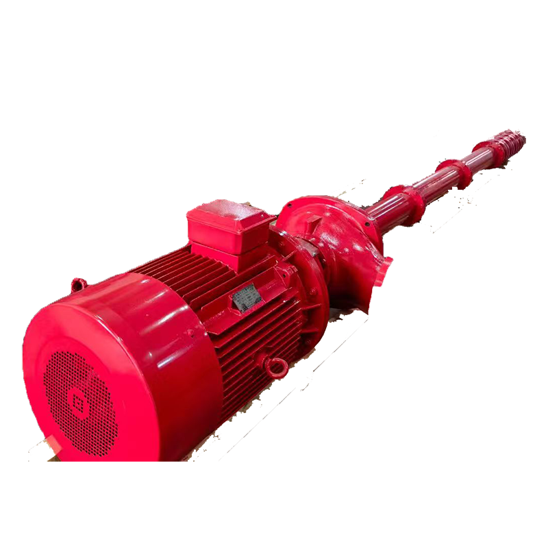
The Wellhead-Motor Driven Vertical Long-Shaft Deep Well Fire Pump Set features modular concentric long-shaft transmission with 304 stainless steel impellers, 20Cr13 shafts, and hard alloy mechanical seals, delivering stable fire water at 5-110 L/s flow and ≤200 m head.
Resolves critical risks in conventional deep-well fire pumps: underwater motor maintenance hazards, shaft vibration/wear, efficiency degradation, and difficult in-well servicing.
Suitable for high-rise fire hydrant systems, industrial fire networks, municipal emergency supply, and combined domestic/fire water systems requiring GB 6245-2006/NFPA 20 compliance for non-corrosive clean water and neutral liquids.
Extended Service Life: 304 stainless steel impeller + 20Cr13 transmission shaft + tungsten carbide mechanical seals resist wear, corrosion & cavitation. Design lifespan ≥15 years—over 40% longer than standard deep-well fire pumps.
Significant Energy Savings: Concentric long-shaft direct drive + optimized hydraulic model achieve ≥78% efficiency at rated duty. Combined with wide high-efficiency range design, annual energy consumption drops by 20%–30% vs. traditional solutions.
Lower Maintenance Costs: Vertical long-shaft design + surface motor layout enables routine maintenance without well entry. Single technician completes seal/bearing replacement within 1.5 hours, reducing labor costs by 50%.
Lightweight & Compact Design: Modular column pipes + lightweight transmission shaft assembly reduce overall weight by ~15% for equivalent head ratings, lowering wellhead load requirements & lifting complexity.
Faster Installation: Pre-aligned flanges + quick-install pump base enable vertical alignment & fixation on-site. Standard units reach commissioning readiness within 3 hours from positioning, compressing deployment cycle by 40%.
Building Fire Protection: Hydrant systems, automatic sprinkler systems, and water mist fire systems for high-rise/super high-rise buildings, commercial complexes, hotels, offices, and residential communities, ensuring stable water supply during power outages.
Industrial Fire Protection: Fire network water supply & process cooling backup for petrochemical, power plants, metallurgy/mining, pharmaceutical, and logistics warehouse facilities, supporting high-flow, high-head continuous operation.
Municipal Facilities: Emergency fire water supply guarantee for critical public infrastructure: hospitals, schools, subway tunnels, airports/ports, and data centers, meeting rapid response demands under complex conditions.
Domestic/Industrial Water Supply: Shared domestic/industrial water systems, building/municipal drainage, fixed fire system integration for industrial/mining enterprises, adapting to non-corrosive clean water & neutral liquid transport.
Media Compatibility: Non-corrosive clean water or neutral liquids with similar physicochemical properties. Solid particles ≤0.01% (by weight), pH 6.5–8.5, H₂S ≤1.5 mg/L, water temperature ≤40℃/104℉.

 | No. | Material Name | Material |
| 1 | Electric Motor | Component | |
| 2 | Motor Support Bracket | QT400-18 | |
| 3 | Motor Coupling | ZG235-450 | |
| 4 | Mechanical Seal Gland | QT400-18 | |
| 5 | Mechanical Seal | WC/SiC | |
| 6 | Seal Positioning Ring | ZG235-450 | |
| 7 | Discharge Head | QT400-18 | |
| 8 | Pump Casing Support Bracket | QT400-18 | |
| 9 | Casing Support Bearing | Asbestos-Metal | |
| 10 | Drive Shaft Coupling | ZG235-450 | |
| 11 | Shaft | 20Cr13 | |
| 12 | Column Pipe Bearing | Asbestos-Metal | |
| 13 | Column Pipe Support Bracket | QT400-18 | |
| 14 | Upper Diffuser | QT400-18 | |
| 15 | Diffuser Bearing | Rubber | |
| 16 | Tapered Sleeve | 20Cr13 | |
| 17 | Impeller | 06Cr19Ni10 | |
| 18 | Intermediate Diffuser | QT400-18 | |
| 19 | Suction Inlet Bearing | Rubber | |
| 20 | Suction Inlet | QT400-18 | |
| 21 | Suction Strainer | 06Cr19Ni10 | |
| 22 | Thrust Disc | 20Cr13 | |
| 23 | Thrust Plate | PTFE Composite |
| No. | Fire Pump Model | Flow Rate | Head | Power | Speed | Nominal Diameter | Maximum Working Pressure | Pressure at 150% Rated Flow |
| 1 | XBD4.0/1WJ-CD |
1 | 40 | 3 | 2850 |
50 | 0.560 | 0.260 |
| 2 | XBD5.0/1WJ-CD | 50 | 4 | 2850 | 0.700 | 0.325 | ||
| 3 | XBD6.0/1WJ-CD | 60 | 4 | 2850 | 0.840 | 0.390 | ||
| 4 | XBD7.0/1WJ-CD | 70 | 5.5 | 2850 | 0.980 | 0.455 | ||
| 5 | XBD8.0/1WJ-CD | 80 | 7.5 | 2850 | 1.120 | 0.520 | ||
| 6 | XBD9.0/1WJ-CD | 90 | 7.5 | 2850 | 1.260 | 0.585 | ||
| 7 | XBD10.0/1WJ-CD | 100 | 7.5 | 2850 | 1.400 | 0.650 | ||
| 8 | XBD11.0/1WJ-CD | 110 | 11 | 2850 | 1.540 | 0.715 | ||
| 9 | XBD12.0/1WJ-CD | 120 | 11 | 2850 | 1.680 | 0.780 | ||
| 10 | XBD13.0/1WJ-CD | 130 | 11 | 2850 | 1.820 | 0.845 | ||
| 11 | XBD14.0/1WJ-CD | 140 | 11 | 2850 | 1.960 | 0.910 | ||
| 12 | XBD15.0/1WJ-CD | 150 | 15 | 2850 | 2.100 | 0.975 | ||
| 13 | XBD16.0/1WJ-CD | 160 | 15 | 2850 | 2.240 | 1.040 | ||
| 14 | XBD16.8/1WJ-CD | 168 | 15 | 2850 | 2.352 | 1.092 | ||
| 15 | XBD4.0/3WJ-CD |
3 | 40 | 3 | 2850 |
50 | 0.560 | 0.260 |
| 16 | XBD5.0/3WJ-CD | 50 | 4 | 2850 | 0.700 | 0.325 | ||
| 17 | XBD6.0/3WJ-CD | 60 | 5.5 | 2850 | 0.840 | 0.390 | ||
| 18 | XBD7.0/3WJ-CD | 70 | 7.5 | 2850 | 0.980 | 0.455 | ||
| 19 | XBD8.0/3WJ-CD | 80 | 7.5 | 2850 | 1.120 | 0.520 | ||
| 20 | XBD9.0/3WJ-CD | 90 | 7.5 | 2850 | 1.260 | 0.585 | ||
| 21 | XBD10.0/3WJ-CD | 100 | 7.5 | 2850 | 1.400 | 0.650 | ||
| 22 | XBD11.0/3WJ-CD | 110 | 11 | 2850 | 1.540 | 0.715 | ||
| 23 | XBD12.0/3WJ-CD | 120 | 11 | 2850 | 1.680 | 0.780 | ||
| 24 | XBD13.0/3WJ-CD | 130 | 11 | 2850 | 1.820 | 0.845 | ||
| 25 | XBD14.0/3WJ-CD | 140 | 11 | 2850 | 1.960 | 0.910 | ||
| 26 | XBD15.0/3WJ-CD | 150 | 15 | 2850 | 2.100 | 0.975 | ||
| 27 | XBD16.0/3WJ-CD | 160 | 15 | 2850 | 2.240 | 1.040 | ||
| 28 | XBD16.8/3WJ-CD | 168 | 15 | 2850 | 2.352 | 1.092 | ||
| 29 | XBD4.0/5WJ-CD | 5 | 40 | 4 | 2850 | 50 | 0.560 | 0.260 |
| 30 | XBD5.0/5WJ-CD | 50 | 5.5 | 2850 | 0.700 | 0.325 |
| No. | Fire Pump Model | Flow Rate | Head | Power | Speed | Nominal Diameter | Maximum Working Pressure | Pressure at 150% Rated Flow |
| 31 | XBD6.0/5WJ-CD |
5 | 60 | 5.5 | 2850 |
50 | 0.840 | 0.390 |
| 32 | XBD7.0/5WJ-CD | 70 | 7.5 | 2850 | 0.980 | 0.455 | ||
| 33 | XBD8.0/5WJ-CD | 80 | 7.5 | 2850 | 1.120 | 0.520 | ||
| 34 | XBD9.0/5WJ-CD | 90 | 11 | 2850 | 1.260 | 0.585 | ||
| 35 | XBD10.0/5WJ-CD | 100 | 11 | 2850 | 1.400 | 0.650 | ||
| 36 | XBD11.0/5WJ-CD | 110 | 11 | 2850 | 1.540 | 0.715 | ||
| 37 | XBD12.0/5WJ-CD | 120 | 15 | 2850 | 1.680 | 0.780 | ||
| 38 | XBD13.0/5WJ-CD | 130 | 15 | 2850 | 1.820 | 0.845 | ||
| 39 | XBD14.0/5WJ-CD | 140 | 15 | 2850 | 1.960 | 0.910 | ||
| 40 | XBD15.0/5WJ-CD | 150 | 18.5 | 2850 | 2.100 | 0.975 | ||
| 41 | XBD16.0/5WJ-CD | 160 | 18.5 | 2850 | 2.240 | 1.040 | ||
| 42 | XBD16.8/5WJ-CD | 168 | 30 | 2850 | 2.352 | 1.092 | ||
| 43 | XBD3.3/5GJ-CD |
5 | 33 | 3 | 2900 |
50 | 0.462 | 0.215 |
| 44 | XBD4.0/5GJ-CD | 40 | 4 | 2900 | 0.560 | 0.260 | ||
| 45 | XBD6.0/5GJ-CD | 60 | 5.5 | 2900 | 0.840 | 0.390 | ||
| 46 | XBD8.0/5GJ-CD | 80 | 7.5 | 2900 | 1.120 | 0.520 | ||
| 47 | XBD10.0/5GJ-CD | 100 | 11 | 2900 | 1.400 | 0.650 | ||
| 48 | XBD12.0/5GJ-CD | 120 | 15 | 2900 | 1.680 | 0.780 | ||
| 49 | XBD14.0/5GJ-CD | 140 | 15 | 2900 | 1.960 | 0.910 | ||
| 50 | XBD16.3/5GJ-CD | 163 | 18.5 | 2900 | 2.282 | 1.060 | ||
| 51 | XBD3.2/10GJ-CD |
10 | 32 | 5.5 | 2900 |
80 | 0.448 | 0.208 |
| 52 | XBD4.2/10GJ-CD | 42 | 7.5 | 2900 | 0.588 | 0.273 | ||
| 53 | XBD5.0/10GJ-CD | 50 | 11 | 2900 | 0.700 | 0.325 | ||
| 54 | XBD6.0/10GJ-CD | 60 | 15 | 2900 | 0.840 | 0.390 | ||
| 55 | XBD8.4/10GJ-CD | 84 | 15 | 2900 | 1.176 | 0.546 | ||
| 56 | XBD9.6/10GJ-CD | 96 | 18.5 | 2900 | 1.344 | 0.624 | ||
| 57 | XBD10.0/10GJ-CD | 100 | 18.5 | 2900 | 1.400 | 0.650 | ||
| 58 | XBD11.0/10GJ-CD | 110 | 18.5 | 2900 | 1.540 | 0.715 | ||
| 59 | XBD12.0/10GJ-CD | 120 | 22 | 2900 | 1.680 | 0.780 | ||
| 60 | XBD13.0/10GJ-CD | 130 | 22 | 2900 | 1.820 | 0.845 |
| No. | Fire Pump Model | Flow Rate | Head | Power | Speed | Nominal Diameter | Maximum Working Pressure | Pressure at 150% Rated Flow |
| 61 | XBD14.4/10GJ-CD |
10 | 144 | 30 | 2900 |
80 | 2.016 | 0.936 |
| 62 | XBD15.6/10GJ-CD | 156 | 30 | 2900 | 2.184 | 1.014 | ||
| 63 | XBD17.0/10GJ-CD | 170 | 37 | 2900 | 2.380 | 1.105 | ||
| 64 | XBD18.0/10GJ-CD | 180 | 37 | 2900 | 2.520 | 1.170 | ||
| 65 | XBD3.6/15GJ-CD |
15 | 36 | 11 | 2900 |
80 | 0.504 | 0.234 |
| 66 | XBD4.0/15GJ-CD | 40 | 11 | 2900 | 0.560 | 0.260 | ||
| 67 | XBD5.0/15GJ-CD | 50 | 15 | 2900 | 0.700 | 0.325 | ||
| 68 | XBD6.0/15GJ-CD | 60 | 15 | 2900 | 0.840 | 0.390 | ||
| 69 | XBD7.2/15GJ-CD | 72 | 18.5 | 2900 | 1.008 | 0.468 | ||
| 70 | XBD8.4/15GJ-CD | 84 | 22 | 2900 | 1.176 | 0.546 | ||
| 71 | XBD9.6/15GJ-CD | 96 | 22 | 2900 | 1.344 | 0.624 | ||
| 72 | XBD10.0/15GJ-CD | 100 | 22 | 2900 | 1.400 | 0.650 | ||
| 73 | XBD11.0/15GJ-CD | 110 | 30 | 2900 | 1.540 | 0.715 | ||
| 74 | XBD12.0/15GJ-CD | 120 | 30 | 2900 | 1.680 | 0.780 | ||
| 75 | XBD13.0/15GJ-CD | 130 | 37 | 2900 | 1.820 | 0.845 | ||
| 76 | XBD14.0/15GJ-CD | 140 | 37 | 2900 | 1.960 | 0.910 | ||
| 77 | XBD15.6/15GJ-CD | 156 | 37 | 2900 | 2.184 | 1.014 | ||
| 78 | XBD17.0/15GJ-CD | 170 | 45 | 2900 | 2.380 | 1.105 | ||
| 79 | XBD18.2/15GJ-CD | 182 | 45 | 2900 | 2.548 | 1.183 | ||
| 80 | XBD20.0/15GJ-CD | 200 | 55 | 2900 | 2.800 | 1.300 | ||
| 81 | XBD3.3/20GJ-CD |
20 | 33 | 11 | 2900 |
100 | 0.462 | 0.215 |
| 82 | XBD4.0/20GJ-CD | 40 | 15 | 2900 | 0.560 | 0.260 | ||
| 83 | XBD4.4/20GJ-CD | 44 | 15 | 2900 | 0.616 | 0.286 | ||
| 84 | XBD5.0/20GJ-CD | 50 | 18.5 | 2900 | 0.700 | 0.325 | ||
| 85 | XBD5.5/20GJ-CD | 55 | 18.5 | 2900 | 0.770 | 0.358 | ||
| 86 | XBD6.0/20GJ-CD | 50 | 22 | 2900 | 0.700 | 0.325 | ||
| 87 | XBD6.6/20GJ-CD | 66 | 22 | 2900 | 0.924 | 0.429 | ||
| 88 | XBD7.0/20GJ-CD | 70 | 30 | 2900 | 0.980 | 0.455 | ||
| 89 | XBD8.0/20GJ-CD | 80 | 30 | 2900 | 1.120 | 0.520 | ||
| 90 | XBD9.0/20GJ-CD | 90 | 30 | 2900 | 1.260 | 0.585 |
| No. | Fire Pump Model | Flow Rate | Head | Power | Speed | Nominal Diameter | Maximum Working Pressure | Pressure at 150% Rated Flow |
| 91 | XBD10.0/20GJ-CD |
20 | 100 | 37 | 2900 |
100 | 1.400 | 0.650 |
| 92 | XBD11.0/20GJ-CD | 110 | 37 | 2900 | 1.540 | 0.715 | ||
| 93 | XBD12.1/20GJ-CD | 121 | 45 | 2900 | 1.694 | 0.787 | ||
| 94 | XBD14.0/20GJ-CD | 140 | 45 | 2900 | 1.960 | 0.910 | ||
| 95 | XBD16.0/20GJ-CD | 160 | 55 | 2900 | 2.240 | 1.040 | ||
| 96 | XBD18.0/20GJ-CD | 180 | 55 | 2900 | 2.520 | 1.170 | ||
| 97 | XBD20.0/20GJ-CD | 200 | 75 | 2900 | 2.800 | 1.300 | ||
| 98 | XBD3.2/25GJ-CD |
25 | 32 | 11 | 2900 |
100 | 0.448 | 0.208 |
| 99 | XBD4.2/25GJ-CD | 42 | 15 | 2900 | 0.588 | 0.273 | ||
| 100 | XBD5.3/25GJ-CD | 53 | 18.5 | 2900 | 0.742 | 0.345 | ||
| 101 | XBD6.3/25GJ-CD | 63 | 22 | 2900 | 0.882 | 0.410 | ||
| 102 | XBD7.3/25GJ-CD | 73 | 30 | 2900 | 1.022 | 0.475 | ||
| 103 | XBD8.4/25GJ-CD | 84 | 37 | 2900 | 1.176 | 0.546 | ||
| 104 | XBD9.0/25GJ-CD | 90 | 37 | 2900 | 1.260 | 0.585 | ||
| 105 | XBD10.0/25GJ-CD | 100 | 37 | 2900 | 1.400 | 0.650 | ||
| 106 | XBD11.0/25GJ-CD | 110 | 45 | 2900 | 1.540 | 0.715 | ||
| 107 | XBD12.0/25GJ-CD | 120 | 45 | 2900 | 1.680 | 0.780 | ||
| 108 | XBD14.0/25GJ-CD | 140 | 55 | 2900 | 1.960 | 0.910 | ||
| 109 | XBD16.0/25GJ-CD | 160 | 75 | 2900 | 2.240 | 1.040 | ||
| 110 | XBD18.5/25GJ-CD | 185 | 75 | 2900 | 2.590 | 1.203 | ||
| 111 | XBD3.6/30GJ-CD |
30 | 36 | 15 | 2900 |
100 | 0.504 | 0.234 |
| 112 | XBD4.0/30GJ-CD | 40 | 18.5 | 2900 | 0.560 | 0.260 | ||
| 113 | XBD5.0/30GJ-CD | 50 | 22 | 2900 | 0.700 | 0.325 | ||
| 114 | XBD6.0/30GJ-CD | 60 | 30 | 2900 | 0.840 | 0.390 | ||
| 115 | XBD7.2/30GJ-CD | 72 | 30 | 2900 | 1.008 | 0.468 | ||
| 116 | XBD8.0/30GJ-CD | 80 | 37 | 2900 | 1.120 | 0.520 | ||
| 117 | XBD9.0/30GJ-CD | 90 | 45 | 2900 | 1.260 | 0.585 | ||
| 118 | XBD10.0/30GJ-CD | 100 | 45 | 2900 | 1.400 | 0.650 | ||
| 119 | XBD11.0/30GJ-CD | 110 | 45 | 2900 | 1.540 | 0.715 | ||
| 120 | XBD13.0/30GJ-CD | 130 | 55 | 2900 | 1.820 | 0.845 |
| No. | Fire Pump Model | Flow Rate | Head | Power | Speed | Nominal Diameter | Maximum Working Pressure | Pressure at 150% Rated Flow |
| 121 | XBD14.5/30GJ-CD |
30 | 145 | 75 | 2900 |
100 | 2.030 | 0.943 |
| 122 | XBD16.2/30GJ-CD | 162 | 75 | 2900 | 2.268 | 1.053 | ||
| 123 | XBD18.0/30GJ-CD | 180 | 90 | 2900 | 2.520 | 1.170 | ||
| 124 | XBD20.0/30GJ-CD | 200 | 90 | 2900 | 2.800 | 1.300 | ||
| 125 | XBD3.2/35GJ-CD |
35 | 32 | 18.5 | 2900 |
100 | 0.448 | 0.208 |
| 126 | XBD4.0/35GJ-CD | 40 | 22 | 2900 | 0.560 | 0.260 | ||
| 127 | XBD5.0/35GJ-CD | 50 | 30 | 2900 | 0.700 | 0.325 | ||
| 128 | XBD6.0/35GJ-CD | 60 | 30 | 2900 | 0.840 | 0.390 | ||
| 129 | XBD6.5/35GJ-CD | 65 | 37 | 2900 | 0.910 | 0.423 | ||
| 130 | XBD7.0/35GJ-CD | 70 | 37 | 2900 | 0.980 | 0.455 | ||
| 131 | XBD8.0/35GJ-CD | 80 | 45 | 2900 | 1.120 | 0.520 | ||
| 132 | XBD9.0/35GJ-CD | 90 | 55 | 2900 | 1.260 | 0.585 | ||
| 133 | XBD10.0/35GJ-CD | 100 | 55 | 2900 | 1.400 | 0.650 | ||
| 134 | XBD11.2/35GJ-CD | 112 | 75 | 2900 | 1.568 | 0.728 | ||
| 135 | XBD13.0/35GJ-CD | 130 | 75 | 2900 | 1.820 | 0.845 | ||
| 136 | XBD15.0/35GJ-CD | 150 | 90 | 2900 | 2.100 | 0.975 | ||
| 137 | XBD16.0/35GJ-CD | 160 | 90 | 2900 | 2.240 | 1.040 | ||
| 138 | XBD18.0/35GJ-CD | 180 | 110 | 2900 | 2.520 | 1.170 | ||
| 139 | XBD19.2/35GJ-CD | 192 | 110 | 2900 | 2.688 | 1.248 | ||
| 140 | XBD20.0/35GJ-CD | 200 | 132 | 2900 | 2.800 | 1.300 | ||
| 141 | XBD3.2/40GJ-CD |
40 | 32 | 18.5 | 2900 |
150 | 0.448 | 0.208 |
| 142 | XBD4.0/40GJ-CD | 40 | 22 | 2900 | 0.560 | 0.260 | ||
| 143 | XBD4.8/40GJ-CD | 48 | 30 | 2900 | 0.672 | 0.312 | ||
| 144 | XBD5.0/40GJ-CD | 50 | 30 | 2900 | 0.700 | 0.325 | ||
| 145 | XBD6.0/40GJ-CD | 60 | 37 | 2900 | 0.840 | 0.390 | ||
| 146 | XBD7.0/40GJ-CD | 70 | 45 | 2900 | 0.980 | 0.455 | ||
| 147 | XBD8.0/40GJ-CD | 80 | 45 | 2900 | 1.120 | 0.520 | ||
| 148 | XBD9.0/40GJ-CD | 90 | 55 | 2900 | 1.260 | 0.585 | ||
| 149 | XBD10.0/40GJ-CD | 100 | 55 | 2900 | 1.400 | 0.650 | ||
| 150 | XBD11.0/40GJ-CD | 110 | 75 | 2900 | 1.540 | 0.715 |
| No. | Fire Pump Model | Flow Rate | Head | Power | Speed | Nominal Diameter | Maximum Working Pressure | Pressure at 150% Rated Flow |
| 151 | XBD12.0/40GJ-CD |
40 | 120 | 75 | 2900 |
150 | 1.680 | 0.780 |
| 152 | XBD14.0/40GJ-CD | 140 | 90 | 2900 | 1.960 | 0.910 | ||
| 153 | XBD15.0/40GJ-CD | 150 | 90 | 2900 | 2.100 | 0.975 | ||
| 154 | XBD16.5/40GJ-CD | 165 | 110 | 2900 | 2.310 | 1.073 | ||
| 155 | XBD18.0/40GJ-CD | 180 | 110 | 2900 | 2.520 | 1.170 | ||
| 156 | XBD20.0/40GJ-CD | 200 | 132 | 2900 | 2.800 | 1.300 | ||
| 157 | XBD3.0/45GJ-CD |
45 | 30 | 22 | 2900 |
150 | 0.420 | 0.195 |
| 158 | XBD4.0/45GJ-CD | 40 | 30 | 2900 | 0.560 | 0.260 | ||
| 159 | XBD5.0/45GJ-CD | 50 | 37 | 2900 | 0.700 | 0.325 | ||
| 160 | XBD6.0/45GJ-CD | 60 | 45 | 2900 | 0.840 | 0.390 | ||
| 161 | XBD7.0/45GJ-CD | 70 | 55 | 2900 | 0.980 | 0.455 | ||
| 162 | XBD8.0/45GJ-CD | 80 | 55 | 2900 | 1.120 | 0.520 | ||
| 163 | XBD9.0/45GJ-CD | 90 | 75 | 2900 | 1.260 | 0.585 | ||
| 164 | XBD10.0/45GJ-CD | 100 | 75 | 2900 | 1.400 | 0.650 | ||
| 165 | XBD3.2/50GJ-CD |
50 | 32 | 22 | 2900 |
150 | 0.448 | 0.208 |
| 166 | XBD4.0/50GJ-CD | 40 | 30 | 2900 | 0.560 | 0.260 | ||
| 167 | XBD4.5/50GJ-CD | 45 | 37 | 2900 | 0.630 | 0.293 | ||
| 168 | XBD5.0/50GJ-CD | 50 | 37 | 2900 | 0.700 | 0.325 | ||
| 169 | XBD6.0/50GJ-CD | 60 | 45 | 2900 | 0.840 | 0.390 | ||
| 170 | XBD7.0/50GJ-CD | 70 | 55 | 2900 | 0.980 | 0.455 | ||
| 171 | XBD8.0/50GJ-CD | 80 | 55 | 2900 | 1.120 | 0.520 | ||
| 172 | XBD9.0/50GJ-CD | 90 | 75 | 2900 | 1.260 | 0.585 | ||
| 173 | XBD10.5/50GJ-CD | 105 | 75 | 2900 | 1.470 | 0.683 | ||
| 174 | XBD12.0/50GJ-CD | 120 | 90 | 2900 | 1.680 | 0.780 | ||
| 175 | XBD14.0/50GJ-CD | 140 | 110 | 2900 | 1.960 | 0.910 | ||
| 176 | XBD15.0/50GJ-CD | 150 | 132 | 2900 | 2.100 | 0.975 | ||
| 177 | XBD17.0/50GJ-CD | 170 | 160 | 2900 | 2.380 | 1.105 | ||
| 178 | XBD18.0/50GJ-CD | 180 | 160 | 2900 | 2.520 | 1.170 | ||
| 179 | XBD20.0/50GJ-CD | 200 | 200 | 2900 | 2.800 | 1.300 |
| No. | Fire Pump Model | Flow Rate | Head | Power | Speed | Nominal Diameter | Maximum Working Pressure | Pressure at 150% Rated Flow |
| 180 | XBD4.0/55GJ-CD |
55 | 40 | 37 | 2900 |
150 | 0.560 | 0.260 |
| 181 | XBD5.0/55GJ-CD | 50 | 45 | 2900 | 0.700 | 0.325 | ||
| 182 | XBD6.0/55GJ-CD | 60 | 55 | 2900 | 0.840 | 0.390 | ||
| 183 | XBD7.0/55GJ-CD | 70 | 55 | 2900 | 0.980 | 0.455 | ||
| 184 | XBD8.0/55GJ-CD | 80 | 75 | 2900 | 1.120 | 0.520 | ||
| 185 | XBD10.0.0/55GJ-CD | 100 | 90 | 2900 | 1.400 | 0.650 | ||
| 186 | XBD4.0/60GJ-CD |
60 | 40 | 37 | 2900 |
150 | 0.560 | 0.260 |
| 187 | XBD5.0/60GJ-CD | 50 | 45 | 2900 | 0.700 | 0.325 | ||
| 188 | XBD6.0/60GJ-CD | 60 | 55 | 2900 | 0.840 | 0.390 | ||
| 189 | XBD7.0/60GJ-CD | 70 | 75 | 2900 | 0.980 | 0.455 | ||
| 190 | XBD8.0/60GJ-CD | 80 | 75 | 2900 | 1.120 | 0.520 | ||
| 191 | XBD9.0/60GJ-CD | 90 | 90 | 2900 | 1.260 | 0.585 | ||
| 192 | XBD10.0/60GJ-CD | 100 | 90 | 2900 | 1.400 | 0.650 | ||
| 193 | XBD12.0/60GJ-CD | 120 | 110 | 2900 | 1.680 | 0.780 | ||
| 194 | XBD14.0/60GJ-CD | 140 | 132 | 2900 | 1.960 | 0.910 | ||
| 195 | XBD16.0/60GJ-CD | 160 | 160 | 2900 | 2.240 | 1.040 | ||
| 196 | XBD18.0/60GJ-CD | 180 | 160 | 2900 | 2.520 | 1.170 | ||
| 197 | XBD20.0/60GJ-CD | 200 | 200 | 2900 | 2.800 | 1.300 | ||
| 198 | XBD3.0/70GJ-CD |
70 | 30 | 37 | 2900 |
150 | 0.420 | 0.195 |
| 199 | XBD4.0/70GJ-CD | 40 | 45 | 2900 | 0.560 | 0.260 | ||
| 200 | XBD5.0/70GJ-CD | 50 | 55 | 2900 | 0.700 | 0.325 | ||
| 201 | XBD6.0/70GJ-CD | 60 | 75 | 2900 | 0.840 | 0.390 | ||
| 202 | XBD7.2/70GJ-CD | 72 | 90 | 2900 | 1.008 | 0.468 | ||
| 203 | XBD8.2/70GJ-CD | 82 | 110 | 2900 | 1.148 | 0.533 | ||
| 204 | XBD9.0/70GJ-CD | 90 | 110 | 2900 | 1.260 | 0.585 | ||
| 205 | XBD10.0/70GJ-CD | 100 | 132 | 2900 | 1.400 | 0.650 | ||
| 206 | XBD13.0/70GJ-CD | 130 | 160 | 2900 | 1.820 | 0.845 | ||
| 207 | XBD15.0/70GJ-CD | 150 | 200 | 2900 | 2.100 | 0.975 | ||
| 208 | XBD3.0/80GJ-CD |
80 | 30 | 37 | 2900 |
150 | 0.420 | 0.195 |
| 209 | XBD4.0/80GJ-CD | 40 | 45 | 2900 | 0.560 | 0.260 | ||
| 210 | XBD5.0/80GJ-CD | 50 | 55 | 2900 | 0.700 | 0.325 | ||
| 211 | XBD6.0/80GJ-CD | 60 | 75 | 2900 | 0.840 | 0.390 |
| No. | Fire Pump Model | Flow Rate | Head | Power | Speed | Nominal Diameter | Maximum Working Pressure | Pressure at 150% Rated Flow |
| 212 | XBD7.2/80GJ-CD | 80 | 72 | 90 | 2900 | 150 | 1.008 | 0.468 |
| 213 | XBD8.2/80GJ-CD | 82 | 110 | 2900 | 1.148 | 0.533 | ||
| 214 | XBD9.0/80GJ-CD | 90 | 110 | 2900 | 1.260 | 0.585 | ||
| 215 | XBD10.0/80GJ-CD | 100 | 132 | 2900 | 1.400 | 0.650 | ||
| 216 | XBD13.0/80GJ-CD | 130 | 160 | 2900 | 1.820 | 0.845 | ||
| 217 | XBD15.0/80GJ-CD | 150 | 200 | 2900 | 2.100 | 0.975 | ||
| 218 | XBD3.0/90GJ-CD |
90 | 30 | 55 | 2900 |
200 | 0.420 | 0.195 |
| 219 | XBD4.0/90GJ-CD | 40 | 75 | 2900 | 0.560 | 0.260 | ||
| 220 | XBD5.0/90GJ-CD | 50 | 75 | 2900 | 0.700 | 0.325 | ||
| 221 | XBD6.0/90GJ-CD | 60 | 90 | 2900 | 0.840 | 0.390 | ||
| 222 | XBD7.0/90GJ-CD | 70 | 110 | 2900 | 0.980 | 0.455 | ||
| 223 | XBD8.0/90GJ-CD | 80 | 110 | 2900 | 1.120 | 0.520 | ||
| 224 | XBD9.0/90GJ-CD | 90 | 132 | 2900 | 1.260 | 0.585 | ||
| 225 | XBD10.2/90GJ-CD | 102 | 160 | 2900 | 1.428 | 0.663 | ||
| 226 | XBD12.0/90GJ-CD | 120 | 200 | 2900 | 1.680 | 0.780 | ||
| 227 | XBD3.0/100GJ-CD |
100 | 30 | 55 | 2900 |
200 | 0.420 | 0.195 |
| 228 | XBD4.0/100GJ-CD | 40 | 75 | 2900 | 0.560 | 0.260 | ||
| 229 | XBD5.0/100GJ-CD | 50 | 75 | 2900 | 0.700 | 0.325 | ||
| 230 | XBD6.0/100GJ-CD | 60 | 90 | 2900 | 0.840 | 0.390 | ||
| 231 | XBD7.0/100GJ-CD | 70 | 110 | 2900 | 0.980 | 0.455 | ||
| 232 | XBD8.0/100GJ-CD | 80 | 132 | 2900 | 1.120 | 0.520 | ||
| 233 | XBD9.0/100GJ-CD | 90 | 160 | 2900 | 1.260 | 0.585 | ||
| 234 | XBD9.8/100GJ-CD | 98 | 200 | 2900 | 1.372 | 0.637 | ||
| 235 | XBD3.0/110GJ-CD |
110 | 30 | 55 | 2900 |
200 | 0.420 | 0.195 |
| 236 | XBD4.0/110GJ-CD | 40 | 75 | 2900 | 0.560 | 0.260 | ||
| 237 | XBD5.0/110GJ-CD | 50 | 90 | 2900 | 0.700 | 0.325 | ||
| 238 | XBD6.0/110GJ-CD | 60 | 110 | 2900 | 0.840 | 0.390 | ||
| 239 | XBD7.0/110GJ-CD | 70 | 132 | 2900 | 0.980 | 0.455 | ||
| 240 | XBD8.0/110GJ-CD | 80 | 160 | 2900 | 1.120 | 0.520 | ||
| 241 | XBD9.0/110GJ-CD | 90 | 160 | 2900 | 1.260 | 0.585 | ||
| 242 | XBD10.0/110GJ-CD | 100 | 200 | 2900 | 1.400 | 0.650 |
Media Requirements • Media type: Non-corrosive clean water or neutral liquids with similar physicochemical properties • Solid content: ≤0.01% (by weight) • Water quality: pH 6.5–8.5; H₂S content ≤1.5 mg/L
Temperature Limits • Media temperature: ≤40°C (≤104°F) • Ambient temperature: ≤40°C (≤104°F)
System Limits • Flow range: 5–110 L/s (79–1743 GPM) • Head range: ≤200 m (≤656 ft) • Power range: 3–200 kW
Installation Limits • Installation: Vertical wellhead installation with horizontally fixed pump base • Transmission: Long-shaft concentric direct drive with bronze-base bearing support
Note: For special conditions (high temperature / strong corrosion / high sand content / ultra-deep wells), please consult our engineering team before selection. Customized pump solutions available.
Mandatory Fire Certification: Strictly manufactured per GB 6245-2006 “Performance Requirements and Test Methods for Fire Pumps”. Passed type testing by China Fire Equipment Quality Supervision & Testing Center. CCCF-certified models available upon request.
International Standard Compliance: Product design complies with NFPA 20 “Standard for the Installation of Stationary Pumps for Fire Protection”. Key performance indicators (flow-head curve, NPSH, vibration/noise) 100% compliant. Bilingual third-party test reports available.
International Quality System: ISO 9001:2015 certified. Core pressure-bearing components evaluated per CE/PED 2014/68/EU, meeting EU/US market entry requirements.
Factory Inspection Standard: Every unit undergoes 1.5× rated pressure hydrostatic test (5-min hold) + long-shaft concentricity calibration (radial runout ≤0.15 mm) + G2.5 dynamic balance calibration, guaranteeing zero-vibration, zero-leakage delivery.
Fast Standard Delivery: Covers flow 5–110 L/s, head ≤200 m, power 3–200 kW mainstream specifications. Standard 304 stainless steel impeller + 20Cr13 transmission shaft + tungsten carbide seals. Technical confirmation within 72 hours.
Deep Customization Capabilities:
Material Upgrade: Wetted parts optional in 316/duplex 2205 stainless steel for high-chloride, mild acid/alkali, or seawater desalination pretreatment conditions.
Transmission System: Optional bronze-base/tungsten carbide bearings, sand-resistant shaft sleeve assembly for sandy water or ultra-deep well (>200 m) conditions.
Structural Adaptation: Custom column pipe length, pump base flange standard switching (GB/ANSI/DIN), wellhead reinforcement brackets, outdoor rain-proof/anti-corrosion coating customization.
Intelligent Expansion: Pre-wired interfaces for pressure/flow/vibration sensors; supports integration with VFD cabinets, IoT remote monitoring, multi-pump rotation modules.
Please contact us for customization inquiries. Our engineering team delivers process proposals within 48 hours.
Installation Key Points:
1.Fix pump base horizontally on wellhead concrete foundation. Tighten anchor bolts symmetrically. Ensure pump shaft verticality ≤0.5 mm/m to prevent seal failure from long-shaft misalignment wear.
2.Connect column pipes via flanges. Install one pipe clamp per 10 m to ensure uniform axial load distribution. Never transmit pipe stress to pump body.
3.Use pre-aligned couplings for transmission shaft connection. Tighten bolts symmetrically per torque requirements. Manually rotate shaft 3 turns after initial installation to confirm no binding.
4.Motor junction box faces outward. Secure cable along well wall. Grounding resistance ≤4 Ω. Prime pump before initial startup. Jog test to verify rotation (clockwise from motor end).
Commissioning Process: Prime & vent → Jog test for direction → No-load run 10 min → Slowly open discharge valve to rated duty → Record current/pressure/vibration/bearing temp data → Acceptance.
Request the “Deep-Well Fire Pump Set Installation & Maintenance Manual” (PDF/English version) for complete dimensional drawings, column pipe connection specs, and commissioning logs.
Q1: How does long-shaft concentric transmission prevent bearing misalignment wear from radial runout?
Uses bronze-base self-lubricating bearings + support guide bearings every 6–8 m. Combined with G2.5 balanced impeller & pre-aligned coupling, tested radial runout ≤0.15 mm, bearing lifespan ≥20,000 hours.
Q2: How does surface motor design enable “maintenance without well entry”?
Motor + pump base integrated at wellhead. After loosening pump base bolts, rotor assembly can be lifted 300–500 mm as a unit, fully exposing mechanical seals/bearings for maintenance without personnel entering the deep well.
Q3: How to protect transmission system with trace solid particles (≤0.01%)?
Standard bronze-base bearings + sand-resistant shaft sleeves. Optional tungsten carbide shaft sleeves + enclosed oil-lubricated components. Tested: transmission efficiency decay ≤2%/year in 0.01% sand content, extending lifespan 3×.
Q4: What structural reinforcements are needed for ultra-deep wells (>200 m)?
Recommendations: ① Upgrade transmission shaft to 304 stainless steel + add guide bearings every 4–6 m; ② Increase column pipe wall thickness by 10%–15%; ③ Reinforce wellhead foundation + add anti-sway brackets. Provide well depth for custom evaluation.
Q5: How do dual certifications (GB 6245-2006 & NFPA 20) ensure fire acceptance?
Product design meets core requirements of both standards: flow-head curve, NPSH, vibration/noise 100% compliant. Supports bilingual third-party test reports, ensuring smooth fire acceptance for domestic & international projects.