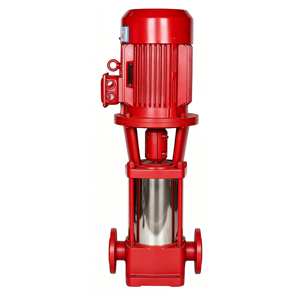
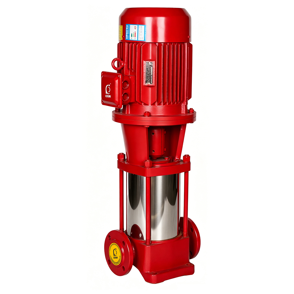
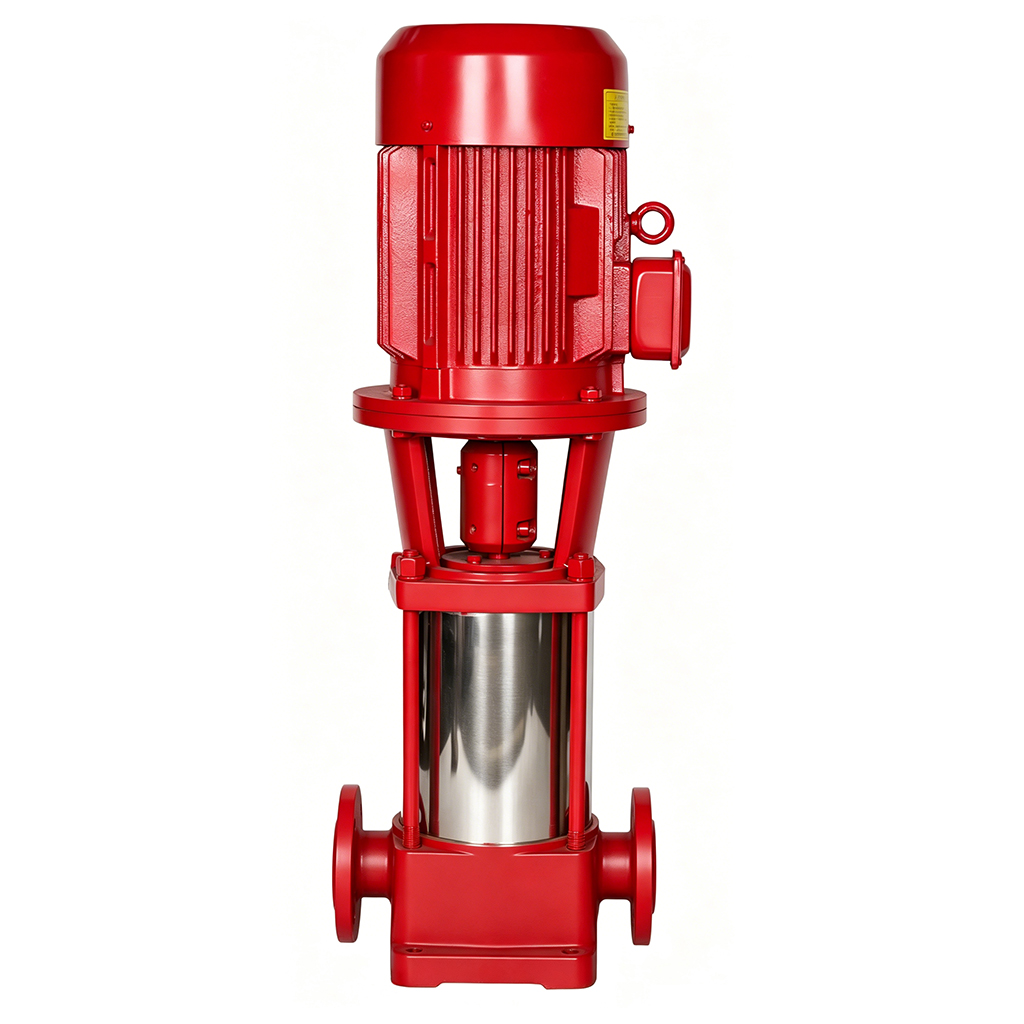
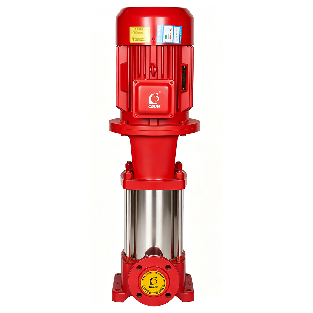
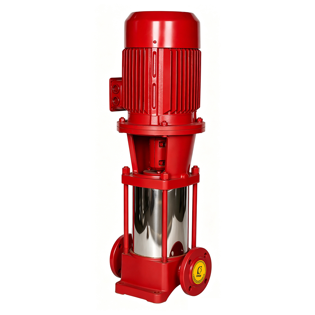
Engineered to GB 6245 national standard with vertical multi-stage hydraulic design, delivering high-head, high-flow, zero-latency emergency water supply and pressure stabilization for fire protection systems.
Precisely deployed for high-rise buildings, commercial complexes, industrial facilities, and municipal fire networks, supporting integrated operation of hydrant, sprinkler, and pressure-stabilization systems.
Unlike standard multi-stage pumps, this series has passed CCCF type testing by the Ministry of Emergency Management. With stainless steel wetted parts, smart inspection interfaces, and wide temperature adaptability (-15℃ to +80℃), it achieves response within ≤30 seconds to rated duty, pressure rating up to 2.5 MPa, and ground-level maintenance accessibility, setting a new industry benchmark for fire pumps.
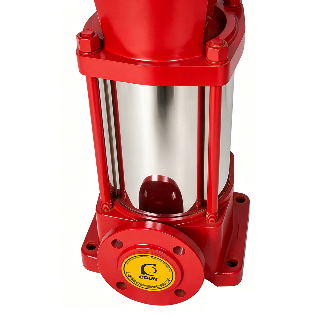
Extended Service Life: Wetted parts in standard 304/316 stainless steel + SiC mechanical seals resist corrosion, wear & cavitation. Design lifespan ≥15 years—over 40% longer than standard cast-iron fire pumps.
Significant Energy Savings: Optimized multi-stage impellers + low-loss diffuser design achieve ≥78% efficiency at rated duty. Combined with VFD pressure stabilization, comprehensive system energy consumption drops by 25%–35% vs. traditional solutions.
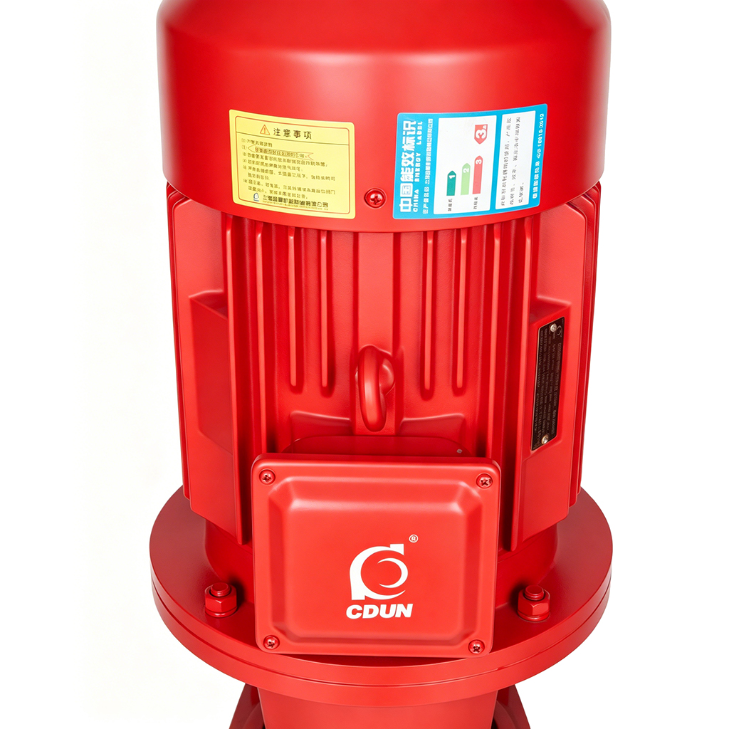
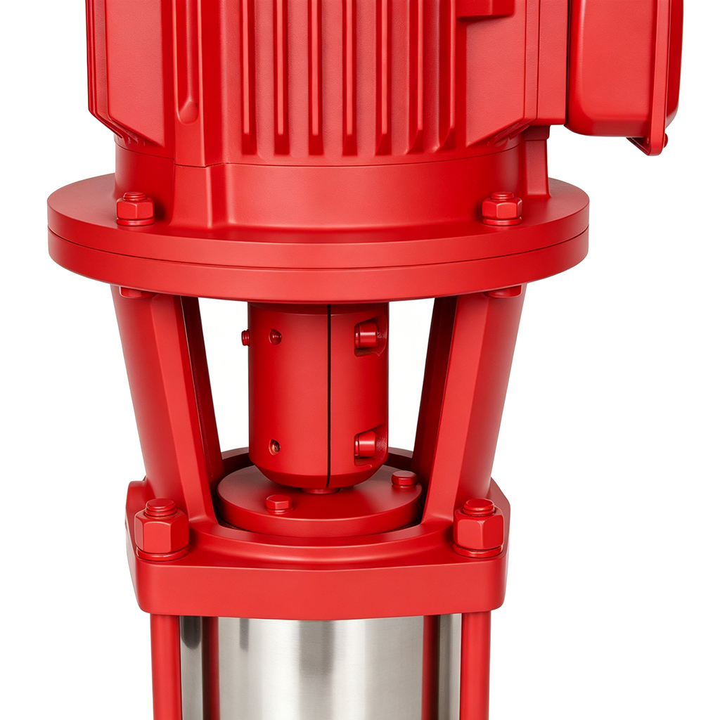
Lower Maintenance Costs: Surface-mounted motor + modular coupling design enables routine inspection/seal replacement without disconnecting piping. One technician completes maintenance within 45 minutes, reducing labor costs by 50%.
Lightweight & Compact Design: Vertical segmented structure eliminates heavy baseplate. Overall weight reduced by ~20% for equivalent head ratings, lowering floor load & lifting complexity.
Faster Installation: Pre-aligned flanges + quick-connect coupling interfaces enable vertical alignment & fixation on-site. Standard units reach commissioning readiness within 3 hours from unboxing, compressing installation cycle by 40%.
High-Rise Building Fire Protection: Hydrant system boosting for residential/office/hotel buildings, automatic sprinkler pressure stabilization, fire tank make-up water linkage.
Commercial Complexes: Zone pressure stabilization for fire networks in shopping malls/convention centers/transport hubs; high-pressure supply for large-space intelligent sprinkler systems.
Industrial & Warehousing: Fire boosting for factory workshops/logistics parks/hazardous material warehouses; foam extinguishing system supply; emergency fire tank circulation.
Municipal & Emergency: End-point boosting for municipal fire networks, temporary fire station supply, mobile emergency pump station integration.
Media Compatibility: Clean water or non-corrosive liquids with similar physicochemical properties. Insoluble solids content ≤0.1% (by mass). Temperature range: -15℃ to +80℃ (5℉ to 176℉).


1-5 L/s Multistage Fire Protection Jockey Pump Structural Diagram
 | No. | Name | Material |
| 1 | Motor | Copper Winding | |
| 2 | Motor Bracket | Ductile Iron | |
| 3 | Coupling | Carbon Steel | |
| 4 | Mechanical Seal | Alloy / Silicon Carbide | |
| 5 | Outlet Guide Vane | Stainless Steel | |
| 6 | Guide Vane | Stainless Steel | |
| 7 | Support Guide Vane | Stainless Steel | |
| 8 | Diffuser | Stainless Steel | |
| 9 | Inlet/Outlet Casing | Ductile Iron | |
| 10 | Pump Bearing | Tungsten Carbide | |
| 11 | Impeller | Stainless Steel | |
| 12 | Shaft | Stainless Steel | |
| 13 | Impeller Spacer | Stainless Steel | |
| 14 | Pressure Casing | Stainless Steel |
5-40 L/s Multistage Fire Pump Structural Diagram
 | No. | Name | Material |
| 1 | Inlet Casing | Ductile Iron | |
| 2 | Bottom Cover | Ductile Iron | |
| 3 | Shaft Sleeve | Cemented Carbide | |
| 4 | Plain Bearing | Wear-resistant Alloy | |
| 5 | Impeller | Stainless Steel | |
| 6 | Impeller Positioning Sleeve | Carbon Steel | |
| 7 | Stage Casing | Ductile Iron | |
| 8 | Guide Vane | Ductile Iron | |
| 9 | Outlet Casing | Ductile Iron | |
| 10 | Connecting Nut | Carbon Steel | |
| 11 | Mechanical Seal | Alloy / Silicon Carbide | |
| 12 | Shaft | Stainless Steel | |
| 13 | Seal Gland | Ductile Iron | |
| 14 | Coupling | Carbon Steel | |
| 15 | Positioning Ring | Stainless Steel | |
| 16 | Motor Adapter | Ductile Iron | |
| 17 | Motor | Copper Winding |
Performance Parameter Table 1
| No. | Model Specification | Rated Flow (L/s) | Rated Head(m) | Rated Power (kw) | Rated Speed (r/min) | Maximum Working Pressure(≤Mpa) | Pressure at 150% of Rated Flow (MPa) |
| 1 | XBD3.2/1W-CDL | 1 | 32 | 0.75 | 2850 | 0.448 | 0.208 |
| 2 | XBD4.0/1W-CDL | 1 | 40 | 1.1 | 2850 | 0.56 | 0.26 |
| 3 | XBD5.0/1W-CDL | 1 | 50 | 1.1 | 2850 | 0.7 | 0.325 |
| 4 | XBD6.0/1W-CDL | 1 | 60 | 1.5 | 2850 | 0.84 | 0.39 |
| 5 | XBD7.2/1W-CDL | 1 | 72 | 2.2 | 2850 | 1.008 | 0.468 |
| 6 | XBD8.1/1W-CDL | 1 | 81 | 2.2 | 2850 | 1.134 | 0.527 |
| 7 | XBD9.0/1W-CDL | 1 | 90 | 2.2 | 2850 | 1.26 | 0.585 |
| 8 | XBD10.3/1W-CDL | 1 | 103 | 3 | 2850 | 1.442 | 0.67 |
| 9 | XBD11.2/1W-CDL | 1 | 112 | 3 | 2850 | 1.568 | 0.728 |
| 10 | XBD12.0/1W-CDL | 1 | 120 | 3 | 2850 | 1.68 | 0.78 |
| 11 | XBD13.0/1W-CDL | 1 | 130 | 3 | 2850 | 1.82 | 0.845 |
| 12 | XBD14.0/1W-CDL | 1 | 140 | 4 | 2850 | 1.96 | 0.91 |
| 13 | XBD15.3/1W-CDL | 1 | 153 | 4 | 2850 | 2.142 | 0.995 |
| 14 | XBD15.8/1W-CDL | 1 | 158 | 4 | 2850 | 2.212 | 1.027 |
| 15 | XBD3.6/2W-CDL | 2 | 36 | 1.5 | 2850 | 0.504 | 0.234 |
| 16 | XBD4.5/2W-CDL | 2 | 45 | 2.2 | 2850 | 0.63 | 0.293 |
| 17 | XBD5.4/2W-CDL | 2 | 54 | 2.2 | 2850 | 0.756 | 0.351 |
| 18 | XBD6.3/2W-CDL | 2 | 63 | 3 | 2850 | 0.882 | 0.41 |
| 19 | XBD7.3/2W-CDL | 2 | 73 | 3 | 2850 | 1.022 | 0.475 |
| 20 | XBD8.1/2W-CDL | 2 | 81 | 4 | 2850 | 1.134 | 0.527 |
| 21 | XBD10.2/2W-CDL | 2 | 102 | 4 | 2850 | 1.428 | 0.663 |
| 22 | XBD11.1/2W-CDL | 2 | 111 | 4 | 2850 | 1.554 | 0.722 |
| 23 | XBD12.0/2W-CDL | 2 | 120 | 5.5 | 2850 | 1.68 | 0.78 |
| 24 | XBD14.0/2W-CDL | 2 | 140 | 5.5 | 2850 | 1.96 | 0.91 |
| 25 | XBD15.0/2W-CDL | 2 | 150 | 5.5 | 2850 | 2.1 | 0.975 |
| 26 | XBD15.8/2W-CDL | 2 | 158 | 7.5 | 2850 | 2.212 | 1.027 |
| 27 | XBD3.0/3W-CDL | 3 | 30 | 2.2 | 2850 | 0.42 | 0.195 |
| 28 | XBD4.0/3W-CDL | 3 | 40 | 3 | 2850 | 0.56 | 0.26 |
| 29 | XBD5.0/3W-CDL | 3 | 50 | 3 | 2850 | 0.7 | 0.325 |
| 30 | XBD6.0/3W-CDL | 3 | 60 | 4 | 2850 | 0.84 | 0.39 |
| 31 | XBD8.0/3W-CDL | 3 | 80 | 5.5 | 2850 | 1.12 | 0.52 |
| 32 | XBD9.0/3W-CDL | 3 | 90 | 5.5 | 2850 | 1.26 | 0.585 |
| 33 | XBD10.0/3W-CDL | 3 | 100 | 7.5 | 2850 | 1.4 | 0.65 |
| 34 | XBD12.0/3W-CDL | 3 | 120 | 7.5 | 2850 | 1.68 | 0.78 |
| 35 | XBD13.0/3W-CDL | 3 | 130 | 7.5 | 2850 | 1.82 | 0.845 |
| 36 | XBD14.0/3W-CDL | 3 | 140 | 11 | 2850 | 1.96 | 0.91 |
| 37 | XBD15.8/3W-CDL | 3 | 158 | 11 | 2850 | 2.212 | 1.027 |
| 38 | XBD3.2/5W-CDL | 5 | 32 | 3 | 2850 | 0.448 | 0.208 |
| 39 | XBD4.0/5W-CDL | 5 | 40 | 4 | 2850 | 0.56 | 0.26 |
| 40 | XBD5.0/5W-CDL | 5 | 50 | 5.5 | 2850 | 0.7 | 0.325 |
| 41 | XBD60/5W-CDL | 5 | 60 | 5.5 | 2850 | 0.84 | 0.39 |
| 42 | XBD7.0/5W-CDL | 5 | 70 | 5.5 | 2850 | 0.98 | 0.455 |
| 43 | XBD8.2/5W-CDL | 5 | 82 | 7.5 | 2850 | 1.148 | 0.533 |
| 44 | XBD9.4/5W-CDL | 5 | 94 | 7.5 | 2850 | 1.316 | 0.611 |
| 45 | XBD10.6/5W-CDL | 5 | 106 | 7.5 | 2850 | 1.484 | 0.689 |
| 46 | XBD12.0/5W-CDL | 5 | 120 | 11 | 2850 | 1.68 | 0.78 |
| 47 | XBD13.0/5W-CDL | 5 | 130 | 11 | 2850 | 1.82 | 0.845 |
| 48 | XBD14.0/5W-CDL | 5 | 140 | 11 | 2850 | 1.96 | 0.91 |
| 49 | XBD15.0/5W-CDL | 5 | 150 | 15 | 2850 | 2.1 | 0.975 |
| 50 | XBD15.8/5W-CDL | 5 | 158 | 18.5 | 2850 | 2.212 | 1.027 |
| No. | Model Specification | Rated Flow (L/s) | Rated Head(m) | Rated Power (kw) | Rated Speed (r/min) | Maximum Working Pressure(≤Mpa) | Pressure at 150% of Rated Flow (MPa) |
| 1 | XBD4.2/5G-GDL | 5 | 42 | 4 | 2900 | 0.588 | 0.252 |
| 2 | XBD5.5/5G-GDL | 5 | 55 | 5.5 | 2900 | 0.77 | 0.33 |
| 3 | XBD6.0/5G-GDL | 5 | 60 | 5.5 | 2900 | 0.84 | 0.36 |
| 4 | XBD7.0/5G-GDL | 5 | 70 | 7.5 | 2900 | 0.98 | 0.42 |
| 5 | XBD8.0/5G-GDL | 5 | 80 | 7.5 | 2900 | 1.12 | 0.48 |
| 6 | XBD10.0/5G-GDL | 5 | 100 | 11 | 2900 | 1.4 | 0.6 |
| 7 | XBD12.0/5G-GDL | 5 | 120 | 11 | 2900 | 1.68 | 0.72 |
| 8 | XBD14.0/5G-GDL | 5 | 140 | 15 | 2900 | 1.96 | 0.84 |
| 9 | XBD4.5/10G-GDL | 10 | 45 | 7.5 | 2900 | 0.63 | 0.27 |
| 10 | XBD6.0/10G-GDL | 10 | 60 | 11 | 2900 | 0.84 | 0.36 |
| 11 | XBD7.0/10G-GDL | 10 | 70 | 11 | 2900 | 0.98 | 0.42 |
| 12 | XBD8.0/10G-GDL | 10 | 80 | 15 | 2900 | 1.12 | 0.48 |
| 13 | XBD9.1/10G-GDL | 10 | 91 | 15 | 2900 | 1.274 | 0.546 |
| 14 | XBD10.2/10G-GDL | 10 | 102 | 18.5 | 2900 | 1.428 | 0.612 |
| 15 | XBD11.0/10G-GDL | 10 | 110 | 18.5 | 2900 | 1.54 | 0.66 |
| 16 | XBD12.0/10G-GDL | 10 | 120 | 18.5 | 2900 | 1.68 | 0.72 |
| 17 | XBD13.0/10G-GDL | 10 | 130 | 22 | 2900 | 1.82 | 0.78 |
| 18 | XBD14.0/10G-GDL | 10 | 140 | 22 | 2900 | 1.96 | 0.84 |
| 19 | XBD4.0/15G-GDL | 15 | 40 | 11 | 2900 | 0.56 | 0.24 |
| 20 | XBD5.0/15G-GDL | 15 | 50 | 15 | 2900 | 0.7 | 0.3 |
| 21 | XBD6.2/15G-GDL | 15 | 62 | 15 | 2900 | 0.868 | 0.372 |
| 22 | XBD8.0/15G-GDL | 15 | 80 | 18.5 | 2900 | 1.12 | 0.48 |
| 23 | XBD9.2/15G-GDL | 15 | 92 | 22 | 2900 | 1.288 | 0.552 |
| 24 | XBD10.0/15G-GDL | 15 | 100 | 22 | 2900 | 1.4 | 0.6 |
| 25 | XBD11.0/15G-GDL | 15 | 110 | 30 | 2900 | 1.54 | 0.66 |
| 26 | XBD12.0/15G-GDL | 15 | 120 | 30 | 2900 | 1.68 | 0.72 |
| 27 | XBD13.0/15G-GDL | 15 | 130 | 30 | 2900 | 1.82 | 0.78 |
| 28 | XBD14.0/15G-GDL | 15 | 140 | 30 | 2900 | 1.96 | 0.84 |
| 29 | XBD16.0/15G-GDL | 15 | 160 | 37 | 2900 | 2.24 | 0.96 |
| 30 | XBD17.0/15G-GDL | 15 | 170 | 45 | 2900 | 2.38 | 1.02 |
| 31 | XBD4.0/20G-GDL | 20 | 40 | 15 | 2900 | 0.56 | 0.24 |
| 32 | XBD6.0/20G-GDL | 20 | 60 | 18.5 | 2900 | 0.84 | 0.36 |
| 33 | XBD7.0/20G-GDL | 20 | 70 | 22 | 2900 | 0.98 | 0.42 |
| No. | Model Specification | Rated Flow (L/s) | Rated Head(m) | Rated Power (kw) | Rated Speed (r/min) | Maximum Working Pressure(≤Mpa) | Pressure at 150% of Rated Flow (MPa) |
| 34 | XBD8.0/20G-GDL | 20 | 80 | 30 | 2900 | 1.12 | 0.48 |
| 35 | XBD9.0/20G-GDL | 20 | 90 | 30 | 2900 | 1.26 | 0.54 |
| 36 | XBD10.0/20G-GDL | 20 | 100 | 30 | 2900 | 1.4 | 0.6 |
| 37 | XBD11.0/20G-GDL | 20 | 110 | 37 | 2900 | 1.54 | 0.66 |
| 38 | XBD12.0/20G-GDL | 20 | 120 | 37 | 2900 | 1.68 | 0.72 |
| 39 | XBD14.0/20G-GDL | 20 | 140 | 45 | 2900 | 1.96 | 0.84 |
| 40 | XBD16.0/20G-GDL | 20 | 160 | 55 | 2900 | 2.24 | 0.96 |
| 41 | XBD17.0/20G-GDL | 20 | 170 | 55 | 2900 | 2.38 | 1.02 |
| 42 | XBD18.0/20G-GDL | 20 | 180 | 55 | 2900 | 2.52 | 1.08 |
| 43 | XBD20.0/20G-GDL | 20 | 200 | 75 | 2900 | 2.8 | 1.2 |
| 44 | XBD21.0/20G-GDL | 20 | 210 | 75 | 2900 | 2.94 | 1.26 |
| 45 | XBD22.0/20G-GDL | 20 | 220 | 90 | 2900 | 3.08 | 1.32 |
| 46 | XBD4.0/25G-GDL | 25 | 40 | 18.5 | 2900 | 0.56 | 0.24 |
| 47 | XBD5.2/25G-GDL | 25 | 52 | 22 | 2900 | 0.728 | 0.312 |
| 48 | XBD6.0/25G-GDL | 25 | 60 | 30 | 2900 | 0.84 | 0.36 |
| 49 | XBD8.0/25G-GDL | 25 | 80 | 37 | 2900 | 1.12 | 0.48 |
| 50 | XBD10.0/25G-GDL | 25 | 100 | 45 | 2900 | 1.4 | 0.6 |
| 51 | XBD11.0/25G-GDL | 25 | 110 | 45 | 2900 | 1.54 | 0.66 |
| 52 | XBD12.3/25G-GDL | 25 | 123 | 55 | 2900 | 1.722 | 0.738 |
| 53 | XBD13.2/25G-GDL | 25 | 132 | 55 | 2900 | 1.848 | 0.792 |
| 54 | XBD14.2/25G-GDL | 25 | 142 | 75 | 2900 | 1.988 | 0.852 |
| 55 | XBD16.0/25G-GDL | 25 | 160 | 75 | 2900 | 2.24 | 0.96 |
| 56 | XBD18.0/25G-GDL | 25 | 180 | 75 | 2900 | 2.52 | 1.08 |
| 57 | XBD20.0/25G-GDL | 25 | 200 | 90 | 2900 | 2.8 | 1.2 |
| 58 | XBD22.0/25G-GDL | 25 | 220 | 110 | 2900 | 3.08 | 1.32 |
| 59 | XBD4.0/30G-GDL | 30 | 40 | 18.5 | 2900 | 0.56 | 0.24 |
| 60 | XBD5.1/30G-GDL | 30 | 51 | 22 | 2900 | 0.714 | 0.306 |
| 61 | XBD6.0/30G-GDL | 30 | 60 | 30 | 2900 | 0.84 | 0.36 |
| 62 | XBD7.0/30G-GDL | 30 | 70 | 30 | 2900 | 0.98 | 0.42 |
| 63 | XBD8.0/30G-GDL | 30 | 80 | 37 | 2900 | 1.12 | 0.48 |
| 64 | XBD9.0/30G-GDL | 30 | 90 | 45 | 2900 | 1.26 | 0.54 |
| 65 | XBD10.0/30G-GDL | 30 | 100 | 45 | 2900 | 1.4 | 0.6 |
| 66 | XBD12.0/30G-GDL | 30 | 120 | 55 | 2900 | 1.68 | 0.72 |
| No. | Model Specification | Rated Flow (L/s) | Rated Head(m) | Rated Power (kw) | Rated Speed (r/min) | Maximum Working Pressure(≤Mpa) | Pressure at 150% of Rated Flow (MPa) |
| 67 | XBD13.0/30G-GDL | 30 | 130 | 55 | 2900 | 1.82 | 0.78 |
| 68 | XBD14.0/30G-GDL | 30 | 140 | 75 | 2900 | 1.96 | 0.84 |
| 69 | XBD16.0/30G-GDL | 30 | 160 | 75 | 2900 | 2.24 | 0.96 |
| 70 | XBD17.0/30G-GDL | 30 | 170 | 75 | 2900 | 2.38 | 1.02 |
| 71 | XBD18.0/30G-GDL | 30 | 180 | 90 | 2900 | 2.52 | 1.08 |
| 72 | XBD20.0/30G-GDL | 30 | 200 | 90 | 2900 | 2.8 | 1.2 |
| 73 | XBD22.0/30G-GDL | 30 | 220 | 110 | 2900 | 3.08 | 1.32 |
| 74 | XBD4.2/35G-GDL | 35 | 42 | 30 | 2900 | 0.588 | 0.252 |
| 75 | XBD6.2/35G-GDL | 35 | 62 | 37 | 2900 | 0.868 | 0.372 |
| 76 | XBD8.3/35G-GDL | 35 | 83 | 45 | 2900 | 1.162 | 0.498 |
| 77 | XBD9.0/35G-GDL | 35 | 90 | 45 | 2900 | 1.26 | 0.54 |
| 78 | XBD10.0/35G-GDL | 35 | 100 | 55 | 2900 | 1.4 | 0.6 |
| 79 | XBD12.0/35G-GDL | 35 | 120 | 75 | 2900 | 1.68 | 0.72 |
| 80 | XBD14.0/35G-GDL | 35 | 140 | 75 | 2900 | 1.96 | 0.84 |
| 81 | XBD16.0/35G-GDL | 35 | 160 | 90 | 2900 | 2.24 | 0.96 |
| 82 | XBD17.0/35G-GDL | 35 | 170 | 90 | 2900 | 2.38 | 1.02 |
| 83 | XBD18.0/35G-GDL | 35 | 180 | 110 | 2900 | 2.52 | 1.08 |
| 84 | XBD20.0/35G-GDL | 35 | 200 | 110 | 2900 | 2.8 | 1.2 |
| 85 | XBD22.0/35G-GDL | 35 | 220 | 132 | 2900 | 3.08 | 1.32 |
| 86 | XBD4.0/40G-GDL | 40 | 40 | 30 | 2900 | 0.56 | 0.24 |
| 87 | XBD6.0/40G-GDL | 40 | 60 | 37 | 2900 | 0.84 | 0.36 |
| 88 | XBD8.0/40G-GDL | 40 | 80 | 45 | 2900 | 1.12 | 0.48 |
| 89 | XBD10.0/40G-GDL | 40 | 100 | 55 | 2900 | 1.4 | 0.6 |
| 90 | XBD12.0/40G-GDL | 40 | 120 | 75 | 2900 | 1.68 | 0.72 |
| 91 | XBD13.0/40G-GDL | 40 | 130 | 75 | 2900 | 1.82 | 0.78 |
| 92 | XBD14.0/40G-GDL | 40 | 140 | 90 | 2900 | 1.96 | 0.84 |
| 93 | XBD16.0/40G-GDL | 40 | 160 | 90 | 2900 | 2.24 | 0.96 |
| 94 | XBD17.0/40G-GDL | 40 | 170 | 90 | 2900 | 2.38 | 1.02 |
| 95 | XBD18.0/40G-GDL | 40 | 180 | 110 | 2900 | 2.52 | 1.08 |
| 96 | XBD20.0/40G-GDL | 40 | 200 | 110 | 2900 | 2.8 | 1.2 |
| 97 | XBD21.0/40G-GDL | 40 | 210 | 132 | 2900 | 2.94 | 1.26 |
| 98 | XBD22.0/40G-GDL | 40 | 220 | 160 | 2900 | 3.08 | 1.32 |
Mandatory Fire Certification: Strictly manufactured per GB 6245-2006 “Performance Requirements and Test Methods for Fire Pumps”. Passed type testing by Fire Product Conformity Assessment Center of Ministry of Emergency Management, certified with CCCF (verifiable certificate number).
Performance Compliance Assurance: Key indicators (flow-head curve, NPSH, vibration/noise, pressure strength) 100% compliant. Third-party full performance curve re-inspection & bilingual (CN/EN) test reports available.International Quality
System: Production follows ISO 9001:2015 QMS. Core pressure-bearing components evaluated per CE/PED 2014/68/EU, meeting EU/US market entry requirements.
Factory Inspection Standard: Every unit undergoes 2.5 MPa hydrostatic test (5-min hold) + G6.3 dynamic balance calibration + no-load running test, guaranteeing zero-leakage, zero-vibration delivery.
Fast Standard Delivery: Covers mainstream specs: flow 5–200 L/s, head 30–300 m. Standard 304 stainless steel + IP55 motors available. Technical confirmation & sample prototyping within 72 hours.Deep Customization Capabilities:
Material Upgrade: Wetted parts optional in 316L, duplex 2205, or PTFE-lined for media with trace particles, mild acids/alkalis, or high chloride
Seals & Motors: Optional high-temperature mechanical seals (>80℃), explosion-proof motors (Ex d IIB T4), IE4 ultra-efficiency or VFD-dedicated motors.
Structural Adaptation: Flange standard switching (GB/ANSI/DIN), reinforced pump base, pre-installed flexible joints, low-noise enclosures.
Intelligent Expansion: Pre-wired interfaces for pressure/flow/level sensors; supports integration with auto fire control cabinets, IoT remote monitoring, auto-inspection rotation modules.
For customization inquiries, please contact us. Our engineering team will provide a tailored process solution within 48 hours.
Pre-Installation Checks: Verify foundation load capacity ≥1.5× pump set full-load weight, maintain ≥600 mm clearance. Confirm media temperature -15℃ to +80℃, solids ≤0.1%. Ambient temp ≤40℃, humidity ≤95% (non-condensing).
Installation Key Points:
1.Mount pump set vertically on solid foundation. Tighten anchor bolts symmetrically. Ensure pump shaft verticality deviation ≤0.5 mm/m to prevent seal failure from misalignment.
2.Connect inlet/outlet with flexible rubber joints. Never transmit pipe stress to pump body. Provide independent supports for inlet/outlet piping.
3.Motor junction box faces outward. Secure cable along pipe wall. Grounding resistance ≤4 Ω. Manually rotate shaft 3 turns before startup.
4.Prime pump & vent air. Jog test to verify rotation (clockwise from motor end). Confirm insulation resistance ≥50 MΩ before operation.
Commissioning Process: Prime & vent → Jog test for direction → No-load run 5 min → Slowly open discharge valve to rated duty → Record current/pressure/vibration/temp rise → Acceptance sign-off.
Request the “Vertical Multi-Stage Fire Pump Set Installation & Maintenance Manual” (PDF/English version) for complete dimensional drawings, flange alignment specs, and commissioning logs.
Q1: How does the fire pump reach rated duty within ≤30 seconds during emergencies?
Features “always-primed + pre-pressurized” design with pump chamber kept water-filled daily. Upon fire alarm, motor starts directly at line frequency. With low-inertia impeller, tested to reach rated flow within 30 seconds, complying with GB 6245 “≤5 min water supply” mandatory requirement.
Q2: What customizations are needed for media temperature >80℃?
Standard type suits -15℃ to +80℃. For >80℃: ① High-temp mechanical seals (FKM O-rings + SiC mating faces); ② Pump body insulation jacket; ③ Enhanced motor cooling. Specify temperature parameters during ordering.
Q3: How does vertical multi-stage design prevent bearing damage from axial overload?
Integrated heavy-duty thrust bearing assembly + hydraulic balance drum automatically balances >90% of axial thrust. Residual axial load is borne by angular contact ball bearings with design lifespan ≥20,000 hours, supporting continuous maintenance-free operation.
Q4: Can CCCF certification be directly used for overseas fire project acceptance?
CCCF is China’s mandatory fire certification. Overseas projects typically require target-market approvals. We provide bilingual test reports, NFPA 20/EN 12845 benchmarking, and assist with CE/UL/FM evaluation.
Q5: How to prevent flow competition & pressure fluctuation during multi-pump parallel operation?
Use identical pumps with independent VFDs. Install check valves & pressure sensors on discharge headers. Control system implements “master-slave rotation + PID closed-loop” algorithm for dynamic load balancing, maintaining pressure fluctuation within ±0.02 MPa.