Traditional self-priming pumps commonly suffer from mechanical seal damage/leakage, cumbersome priming with foot valves, dry-run burnout risks, and short lifespan in high-corrosion conditions, significantly compromising continuous operational reliability & O&M costs in petrochemical/power/environmental harsh applications.
This series resolves these challenges with seal-free multi-face centrifugal dynamic sealing + electric air control valve permanent self-priming system + triple protection (temp/pressure/wear resistance), completely eliminating leakage risks & priming dependency for “first prime, permanent self-priming”, zero-maintenance, low-noise, high-efficiency safe & reliable operation.
Precisely deployed for petrochemical acid/alkali transport, power desulfurization slurry, environmental sewage/sludge, pharmaceutical/food clean fluids, and mining high-concentration solid-liquid transport across 15+ industries, supporting wide-range conditions: flow 5.6–1600 m³/h, head 10–125 m, self-priming height 4–6 m, media temperature ≤120℃ (custom). Achieving 50%+ O&M cost reduction, zero-leakage compliance, and high reliability, setting a new industry benchmark for seal-free automatic self-priming pumps.
Extended Service Life: Seal-free dynamic sealing + wear-resistant alloys. Lifespan ≥15y—10× longer than mechanical seal pumps.
Significant Energy Savings: Zero-friction seal-free design + optimized hydraulics. Efficiency ≥78%, energy consumption ↓20–30% with permanent self-priming.
Lower Maintenance Costs: Permanent self-priming eliminates foot valve/priming/seal replacement. Inspection in 1h, labor costs ↓50%+.
Lightweight & Compact Design: Seal-free structure eliminates heavy seal chamber. Weight ↓~22%, reducing installation & lifting costs.
Faster Installation: Pre-aligned base + quick-connect flanges enable zero-cutting installation. Commissioning ready in 1.5h, cycle ↓45%.
Petrochemical: Acid/alkali/solvent/oil transport. Seal-free, zero-leakage, corrosion/wear resistant.
Power & Metallurgy: Desulfurization slurry/cooling water/coking wastewater. Permanent self-priming prevents dry-run.
Environmental & Municipal: Sewage/sludge/fire drainage. Auto self-priming + non-clogging impeller for emergency response.
Pharmaceutical & Food: Pharma liquids/beverages/pure water. 304/316L optional, GMP compliant.
Mining: High-concentration slurry/tailings/mud. Wear-resistant alloy + large-particle passage.
Media: Clean water/acids/alkalis/solvents/slurry. Temp: ≤50℃ (std) / ≤120℃ (custom). No long fibers.
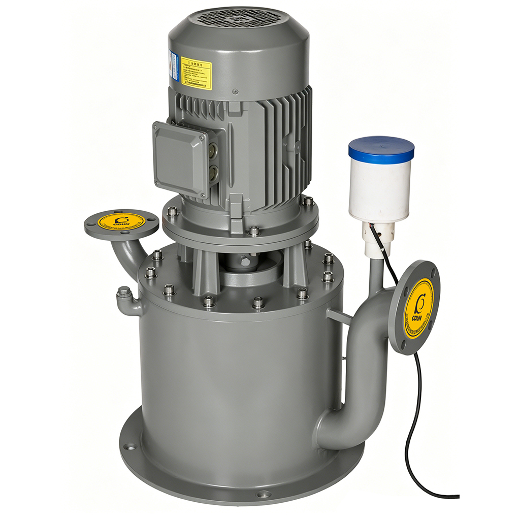
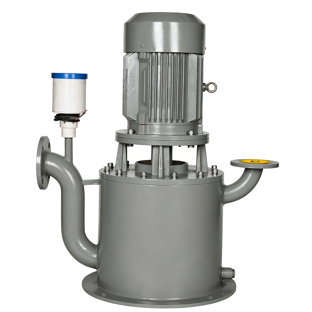
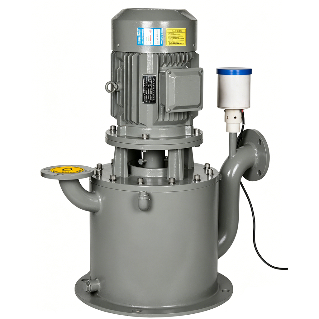
 Product Structure Diagram
 | NO | Component |
| 1 | Motor | |
| 2 | Discharge Check Valve | |
| 3 | Casing Cover | |
| 4 | Diffuser | |
| 5 | Impeller | |
| 6 | Casing | |
| 7 | Air Vent | |
| 8 | Auxiliary Impeller | |
| 9 | Overflow Pipe | |
| 10 | Solenoid Valve | |
| 11 | Shaft |
| Pump Model | Speed n(r/min) | Flow Rate Q(m³/h) | HeadH(m) | Motor Power (kW) | Max. Suction Lift (m) | Inlet Size (mm) | Outlet Size (mm) | Weight (kg) |
| 50WFB11.2-10 | 2960 | 6.7 | 10.9 | 1.5 | 5 | 50 | 40 | 102 |
| 11.2 | 10 | |||||||
| 13.4 | 9.3 | |||||||
| 50WFB12.5-12.5 | 2960 | 7.5 | 13.6 | 2.2 | 5 | 50 | 40 | 110 |
| 12.5 | 12.5 | |||||||
| 15 | 11.6 | |||||||
| 50WFB11.2-16 | 2960 | 6.7 | 17.6 | 2.2 | 5 | 50 | 40 | 113 |
| 11.2 | 16 | |||||||
| 13.4 | 14.8 | |||||||
| 50WFB12.5-20 | 2960 | 7.5 | 22 | 3 | 5 | 50 | 40 | 115 |
| 12.5 | 20 | |||||||
| 15 | 18.5 | |||||||
| 50WFB11.2-25 | 2960 | 6.7 | 27.4 | 4 | 5 | 50 | 40 | 147 |
| 11.2 | 25 | |||||||
| 13.4 | 23.7 | |||||||
| 50WFB12.5-32 | 2960 | 7.5 | 34.3 | 5.5 | 5 | 50 | 40 | 200 |
| 12.5 | 32 | |||||||
| 15 | 29.6 | |||||||
| 50WFB11.2-40 | 2960 | 6.7 | 42 | 7.5 | 5 | 50 | 40 | 177 |
| 11.2 | 40 | |||||||
| 13.4 | 38.4 | |||||||
| 50WFB12.5-50 | 2960 | 7.5 | 52.5 | 11 | 5 | 50 | 40 | 230 |
| 12.5 | 50 | |||||||
| 15 | 48 | |||||||
| 50WFB12.5-64 | 2960 | 7.5 | 66 | 15 | 4 | 50 | 40 | 360 |
| 12.5 | 64 | |||||||
| 15 | 62 | |||||||
| 65WFB22.5-10 | 2960 | 13.5 | 11.3 | 2.2 | 5 | 65 | 50 | 130 |
| 22.5 | 10 | |||||||
| 27 | 9 | |||||||
| 65WFB25-12.5 | 2960 | 15 | 14.1 | 3 | 5 | 65 | 50 | 130 |
| 25 | 12.5 | |||||||
| 30 | 11.3 | |||||||
| 65WFB22.5-16 | 2960 | 13.5 | 17.4 | 4 | 5 | 65 | 50 | 165 |
| 22.5 | 16 | |||||||
| 27 | 14.8 | |||||||
| 65WFB25-20 | 2960 | 15 | 21.8 | 5.5 | 5 | 65 | 50 | 185 |
| 25 | 20 | |||||||
| 30 | 18.5 | |||||||
| 65WFB22.5-25 | 2960 | 13.5 | 28 | 5.5 | 5 | 65 | 50 | 203 |
| 22.5 | 25 | |||||||
| 27 | 24 | |||||||
| 65WFB25-32 | 2960 | 15 | 35 | 7.5 | 5 | 65 | 50 | 222 |
| 25 | 32 | |||||||
| 30 | 30 | |||||||
| 65WFB22.5-40 | 2960 | 13.5 | 42.4 | 11 | 5 | 65 | 50 | 314 |
| 22.5 | 40 | |||||||
| 27 | 37.6 | |||||||
| 65WFB25-50 | 2960 | 15 | 53 | 15 | 5 | 65 | 50 | 322 |
| 25 | 50 | |||||||
| 30 | 47 |
| Pump Model | Speed n(r/min) | Flow Rate Q(m³/h) | HeadH(m) | Motor Power (kW) | Max. Suction Lift (m) | Inlet Size (mm) | Outlet Size (mm) | Weight (kg) |
| 100WFB90-25 | 2960 | 54 | 28.8 | 18.5 | 5 | 100 | 80 | 300 |
| 90 | 25 | |||||||
| 108 | 22.4 | |||||||
| 100WFB100-32 | 2960 | 60 | 36 | 22 | 5 | 100 | 80 | 331 |
| 100 | 32 | |||||||
| 120 | 28 | |||||||
| 100WFB90-40 | 2960 | 54 | 43.2 | 30 | 5 | 100 | 80 | 560 |
| 90 | 40 | |||||||
| 108 | 37.6 | |||||||
| 100WFB100-50 | 2960 | 60 | 54 | 37 | 5 | 100 | 80 | 567 |
| 100 | 50 | |||||||
| 120 | 47 | |||||||
| 100WFB90-64 | 2960 | 54 | 69.6 | 55 | 5 | 100 | 80 | 710 |
| 90 | 64 | |||||||
| 108 | 59.6 | |||||||
| 100WFB100-80 | 2960 | 60 | 87 | 75 | 5 | 100 | 80 | 786 |
| 100 | 80 | |||||||
| 120 | 74.5 | |||||||
| 100WFB90-100 | 2960 | 54 | 106.4 | 75 | 4 | 100 | 80 | 890 |
| 90 | 100 | |||||||
| 108 | 94.4 | |||||||
| 125 WFB150-16 | 2960 | 90 | 18 | 18.5 | 5 | 125 | 100 | 417 |
| 150 | 16 | |||||||
| 180 | 13.5 | |||||||
| 125WFB135-20 | 2960 | 80 | 24 | 22 | 5 | 125 | 100 | 555 |
| 135 | 20 | |||||||
| 160 | 16.5 | |||||||
| 125 WFB150-25 | 2960 | 80 | 30 | 30 | 5 | 125 | 100 | 570 |
| 150 | 25 | |||||||
| 180 | 20.6 | |||||||
| 125 WFB135-32 | 2960 | 80 | 36 | 30 | 5 | 125 | 100 | 570 |
| 135 | 32 | |||||||
| 160 | 28 | |||||||
| 125WFB150-40 | 2960 | 90 | 45 | 45 | 5 | 125 | 100 | 646 |
| 150 | 40 | |||||||
| 180 | 35 | |||||||
| 125 WFB135-50 | 2960 | 80 | 54 | 55 | 5 | 125 | 100 | 868 |
| 135 | 50 | |||||||
| 160 | 47 | |||||||
| 125 WFB150-64 | 2960 | 90 | 69 | 75 | 5 | 125 | 100 | 930 |
| 150 | 64 | |||||||
| 180 | 60 | |||||||
| 105WFB180-10 | 1480 | 108 | 12 | 15 | 6 | 150 | 125 | 465 |
| 180 | 10 | |||||||
| 216 | 8.2 | |||||||
| 150WFB200-12.5 | 1480 | 120 | 15 | 18.5 | 6 | 150 | 125 | 550 |
| 200 | 12.5 | |||||||
| 240 | 10.3 |
| Pump Model | Speed n(r/min) | Flow Rate Q(m³/h) | HeadH(m) | Motor Power (kW) | Max. Suction Lift (m) | Inlet Size (mm) | Outlet Size (mm) | Weight (kg) |
| 200 WFB270-50 | 1480 | 162 | 57 | 110 | 6 | 200 | 150 | 1650 |
| 270 | 50 | |||||||
| 324 | 47.8 | |||||||
| 200 WFB300-64 | 1480 | 180 | 70.4 | 132 | 6 | 200 | 150 | 1800 |
| 300 | 64 | |||||||
| 360 | 59 | |||||||
| 200 VFB400-12.5 | 1480 | 240 | 14.1 | 30 | 6 | 200 | 150 | 749 |
| 400 | 12.5 | |||||||
| 460 | 10.5 | |||||||
| 200 WFB360-16 | 1480 | 216 | 17.2 | 37 | 6 | 200 | 150 | 1000 |
| 360 | 16 | |||||||
| 414 | 14 | |||||||
| 200 WFB400-20 | 1480 | 240 | 21.5 | 55 | 6 | 200 | 150 | 1087 |
| 400 | 20 | |||||||
| 460 | 17.5 | |||||||
| 200 WFB360-25 | 1480 | 216 | 29.6 | 55 | 6 | 200 | 150 | 1200 |
| 360 | 25 | |||||||
| 414 | 22.8 | |||||||
| 200 WFB400-32 | 1480 | 240 | 37 | 90 | 6 | 200 | 150 | 1360 |
| 400 | 32 | |||||||
| 460 | 28.5 | |||||||
| 200 WFB360-40 | 1480 | 216 | 44 | 90 | 6 | 200 | 150 | 1340 |
| 360 | 40 | |||||||
| 414 | 36 | |||||||
| 200 WFB400-50 | 1480 | 240 | 55 | 132 | 6 | 200 | 150 | 1576 |
| 400 | 50 | |||||||
| 460 | 45 | |||||||
| 200 WFB360-64 | 1480 | 216 | 70.4 | 160 | 6 | 200 | 150 | 1900 |
| 360 | 64 | |||||||
| 414 | 59 | |||||||
| 200 WFB400-80 | 1480 | 240 | 88 | 200 | 6 | 200 | 150 | 2100 |
| 400 | 80 | |||||||
| 460 | 74 | |||||||
| 250 WFB550-16 | 1480 | 330 | 18 | 45 | 6 | 250 | 200 | 1100 |
| 550 | 16 | |||||||
| 630 | 13.4 | |||||||
| 250 WFB500-20 | 1480 | 300 | 22 | 55 | 6 | 250 | 200 | 1150 |
| 500 | 20 | |||||||
| 570 | 17.8 | |||||||
| 250 WFB550-25 | 1480 | 330 | 27.1 | 75 | 6 | 250 | 200 | 1200 |
| 550 | 25 | |||||||
| 630 | 22 | |||||||
| 250 WFB500-32 | 1480 | 300 | 37.3 | 90 | 6 | 250 | 200 | 1400 |
| 500 | 32 | |||||||
| 570 | 28.5 |
| Pump Model | Speed n(r/min) | Flow Rate Q(m³/h) | HeadH(m) | Motor Power (kW) | Max. Suction Lift (m) | Inlet Size (mm) | Outlet Size (mm) | Weight (kg) |
| 350WFB860-44 | 1480 | 602 | 46.6 | 200 | 6 | 350 | 300 | 3120 |
| 860 | 44 | |||||||
| 1032 | 38 | |||||||
| 350WFB960-50 | 1480 | 672 | 53 | 280 | 6 | 350 | 300 | 3250 |
| 960 | 50 | |||||||
| 1152 | 44 | |||||||
| 400WFB1400-20 | 980 | 1010 | 25 | 160 | 6 | 400 | 350 | 3600 |
| 1400 | 20 | |||||||
| 1600 | 15 | |||||||
| 400WFB1600-22.5 | 980 | 1200 | 26 | 200 | 6 | 400 | 350 | 3800 |
| 1600 | 22.5 | |||||||
| 1800 | 15 | |||||||
| Note: Performance data based on standard conditions (1 atm, clean water @ 20℃). Correct for non-standard conditions per Operation Manual. Self-priming height: vertical elevation from static liquid surface to pump suction centerline. | ||||||||
Performance Limits • Flow range: 5.6–1600 m³/h (93–26,680 GPM) • Head range: 10–125 m (33–410 ft) • Self-priming height: 4–6 m (13–20 ft, at ambient pressure) • Speed: 2960/1480 rpm (dual-speed optional)
Temperature Limits • Media temperature: ≤50℃ (≤122℉, standard) / ≤120℃ (≤248℉, high-temp custom) • Ambient temperature: ≤40℃ (≤104℉)
Media Requirements • Media type: Clean water / Acids/alkalis / Solvents / Slurry / Sludge • Solid content: General suspended solids, no long fibers
Installation Limits • Inlet/outlet diameter: DN50–DN400 (flange standard GB/T 17241.6) • Installation: Horizontal base (vertical/explosion-proof customizable)
Note: For special conditions (high viscosity/strong corrosion/high altitude/explosion-proof), please consult before selection. Custom solutions available – Please contact us.
National Standard Compliance: Strictly manufactured per GB/T 5657-2013 & JB/T 4126-2013 “Self-priming pumps”. Hydraulic performance & mechanical safety 100% compliant. Third-party full performance curve test reports available.
Zero-Leakage Environmental Certification: Seal-free dynamic sealing structure passes petrochemical industry zero-leakage acceptance standards, eliminating “run-drip-leak”, compliant with GB 31570-2015 petroleum chemical industry pollutant emission standards.
International Quality System: ISO 9001:2015 certified. Core pressure-bearing components evaluated per CE/PED 2014/68/EU, meeting EU/US market entry requirements.
Factory Inspection Standard: Every unit undergoes 1.5× rated pressure hydrostatic test (5-min hold) + self-priming performance test (4–6 m height/≤3 min priming) + vibration/noise test (≤70 dB(A)), guaranteeing zero-leakage, low-noise delivery.
Fast Standard Delivery: Covers flow 5.6–1600 m³/h, head 10–125 m. Standard cast iron/304 stainless steel + multi-face dynamic sealing. Technical confirmation & sample prototyping within 72 hours.
Deep Customization Capabilities:
Material Upgrade: Wetted parts optional in 316/duplex 2205 stainless steel/wear-resistant alloy/PTFE-lined for strong acids/alkalis, high-chloride, or high-wear conditions.
Seals & Motors: Optional high-temp dynamic sealing (up to 120℃), explosion-proof motors (Ex d IIB T4), IE4 ultra-efficiency or VFD-dedicated drives.
Structural Adaptation: Vertical/horizontal layout switching, flange standard switching (GB/ANSI/DIN), explosion-proof configuration/outdoor rain-proof canopy customization.
Intelligent Expansion: Pre-wired interfaces for level/pressure/dry-run sensors; supports integration with PLC automation, IoT remote monitoring, multi-pump rotation modules.
Please contact us for customization inquiries. Our engineering team delivers process proposals within 48 hours.
Installation Key Points:
1.Mount pump horizontally on solid base. Tighten anchor bolts symmetrically. Ensure shaft horizontal deviation ≤0.05 mm/m to prevent excessive vibration from uneven loading.
2.Connect inlet/outlet with flexible rubber joints. Never transmit pipe stress to pump body. Provide independent supports for inlet/outlet piping.
3.Before first use, inject priming water (~1/3 pump chamber volume), open electric air control valve, confirm no pipeline leakage.
4.Jog test to verify motor rotation (clockwise from motor end). Confirm insulation resistance ≥50 MΩ before operation. Observe self-priming completes within ≤3 minutes.
Commissioning Process: Prime injection → Jog test for direction → Start self-priming → After reaching rated duty, record current/pressure/vibration/noise data → Acceptance sign-off.
Request the “WFB Series Seal-Free Automatic Self-Priming Pump Installation & Maintenance Manual” (PDF/English version) for complete dimensional drawings, piping diagrams, and commissioning logs.
Q1: How does seal-free dynamic sealing achieve “zero leakage”?
Multi-face centrifugal dynamic sealing uses centrifugal force to form a dynamic liquid seal barrier with zero mechanical contact friction, completely eliminating “run-drip-leak”, extending lifespan 10×+ vs. mechanical seals.
Q2: How does permanent self-priming achieve “maintenance-free after first prime”?
Electric air control valve + vacuum pump principle integration auto-cuts siphon after first prime. Subsequent startups require no priming, achieving permanent self-priming with zero maintenance.
Q3: How to ensure stable priming at 4–6 m self-priming height?
Optimized pump chamber volume + precision gas-liquid separation structure, combined with electric air control valve for rapid air exhaust. Tested: 4–6 m self-priming height completes priming within ≤3 minutes under ambient pressure conditions.
Q4: How to protect wetted parts against high-wear media (e.g., slurry)?
Standard wear-resistant alloy wetted parts (hardness ≥HRC58), optional ceramic coating/SiC lining. Tested: wear rate reduced by 60%+ in high-concentration slurry conditions.
Q5: What customizations are needed for high-temperature variant (≤120℃)?
Standard suits ≤50℃. For >50℃: ① High-temp dynamic sealing (special alloy + SiC); ② Pump body insulation jacket; ③ Enhanced motor cooling + high-temp bearings.